120
- Test voltage for all insulation measu-
rements - 500 V DC
- The mains switch must be switched
on during the measurement
- The insulation resistance must not be
below the limit values shown in the
table below
- The welding torch must not be con-
nected during the measurement
- Power sources with cooling circuits
must be checked with no coolant in
the system
- The lowest measured value must be
entered in the test record
IMPORTANT! If no conductive connection
exists between the mains plug contacts
during the measurement, then the measu-
rement must be performed on every line.
Insulation resis-
tance
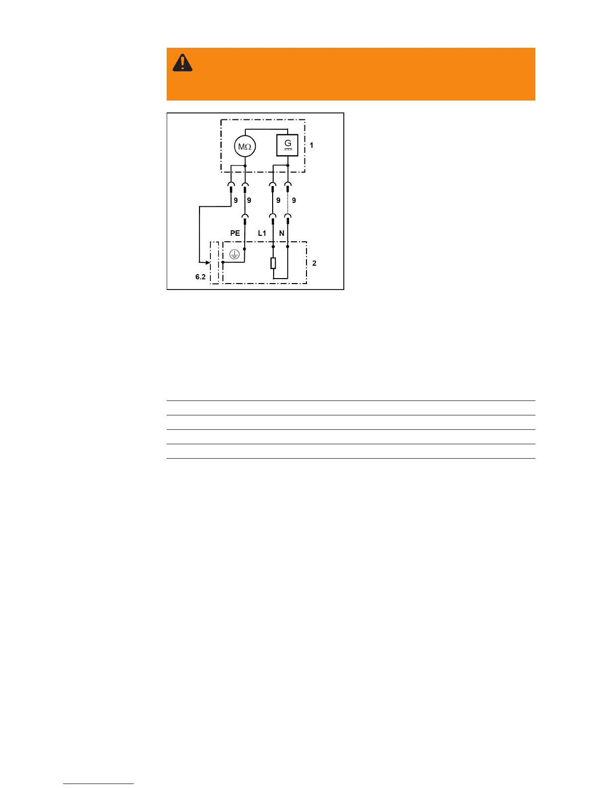
1 Measuring device
2 Welding system
9 Instrument leads
WARNING! Danger of electric shock! The test voltage is 500 V DC. Do not
touch the test piece during the test. Following the test, discharge the capaci-
tors between secondary / earth and primary / earth using a suitable resistance
(e.g.: 10 kΩ / 5 W).
Measurement Limit value
Primary - Secondary Mains plug L1, L2, L3, N -> Current sockets ≥ 5 MΩ
Primary - Earth (PE) Mains plug L1, L2, L3, N -> Earth ≥ 2.5 MΩ
Secondary - Earth (PE) Current sockets -> Earth ≥ 2.5 MΩ
IMPORTANT! If no conductive connection exists between the welding current sockets
during the measurement, then the measurement must be performed on every current
socket.
- Peak value measurement of open circuit voltage at the power source current
sockets
- The measurement must be performed using the „Measuring circuit for U
0
measure-
ment“
- The measurement must be performed in „Electrode“ mode
- The open circuit voltage may not exceed the value specified on the rating plate for
a power source supply at rated welding voltage
Performing the measurement:
- Connect the measuring circuit and the multimeter to the power source
- Set the multimeter to DC voltage measurement and the measuring circuit to U
peak
- Briefly press the Reset button to discharge the capacitors
- Adjust the potentiometer until the largest voltage value is shown
Open circuit
voltage U
0

 Loading...