79
EN
Function over-
view
- Digital adjuster with power module (flow converter) for the wire-feed unit motor
- two-stage adjustment for permanent stabilisation of the motor:
a) Stabilisation of fast, dynamic changes, using a voltage/current regulator
b) Stabilisation of slow, dynamic changes, using a speed controller via the actual-
value pick-up
- Controls the wire-feed unit via PWM signal
- Full bridge for controlling the motor, changing the motor’s direction of rotation and
for controlled accelerating and decelerating
- The switched mode supply on the SR 41 is supplied with 24 V from outside the
power source, and ensures an independent supply for the PC board, and supply for
any connected peripheral devices with voltages of +15 V, -15 V and + 5 V .
- Controls the gas magnet valve, „blow-off“ signal
- Controls a push-pull system via the X12 plug
- Analyses the torch trigger signal
- Analyses the actual rotational speed value of the wire-feed unit motor,
- Analyses the robot sensor signals (e.g. wire end)
- 3 LocalNet interfaces for communicating between SR 41, power source, remote
control and options:
a) X2 for internal components (e.g.: control panel)
b) X6 for external components (e.g.: remote control)
c) X7 for the power source
Overvoltage protection (varistors) and overcurrent protection (PTC) on all LocalNet
interfaces, except X2
- Firmware update using BSL tool via programming connection X9
Technical Data
Supply voltage (from NT 24) + 24 V DC
Supply voltage (from NT 60) + 55 V DC
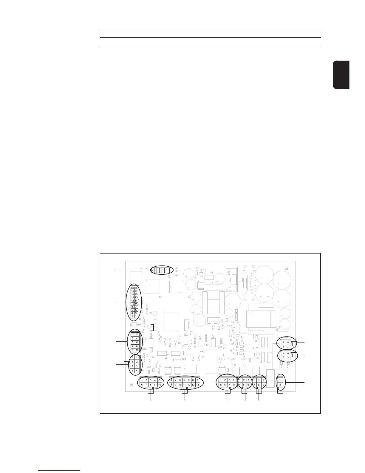
Plug layout
(X10)
(X4)(X3)
(X9)
(X6)
(X11)
(X1)
(X7)
(X8)
(X5)
(X2)
Fig. 55 Plug on SR 41 PC board
(X12)

 Loading...