56
LED checklist of
power module
PC boards
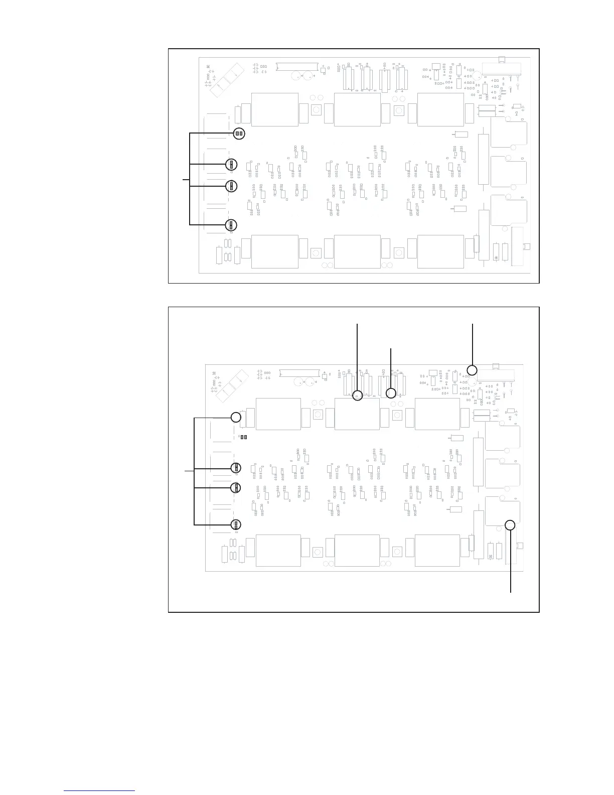
Fig. 22 LED indicators on PC board BPS 50 < V1.4A, BPS 42 < V1.4A, BPS 40, BPS 32
8 transistor module control LEDs
8 transistor module control LEDs
Fig. 22a LED indicators on PC board BPS 53, BPS 50 >/= V1.4A, BPS 43, BPS 42 >/= V1.4A
Main switch LED
Intermediate circuit
imbalance LED
LED +15 V primary
High charging relay LED
Measuring points In every transistor module there are 4 MOS-FETs (metal oxide semiconductor field
effect transistors) with diode. This diode provides information about the state of the
transistor:
using a diode tester, a diffusion potential of 0.4 - 0.5 V must be measured. If this voltage
cannot be measured, the module is faulty.

 Loading...