53
EN
Overview
(continued)
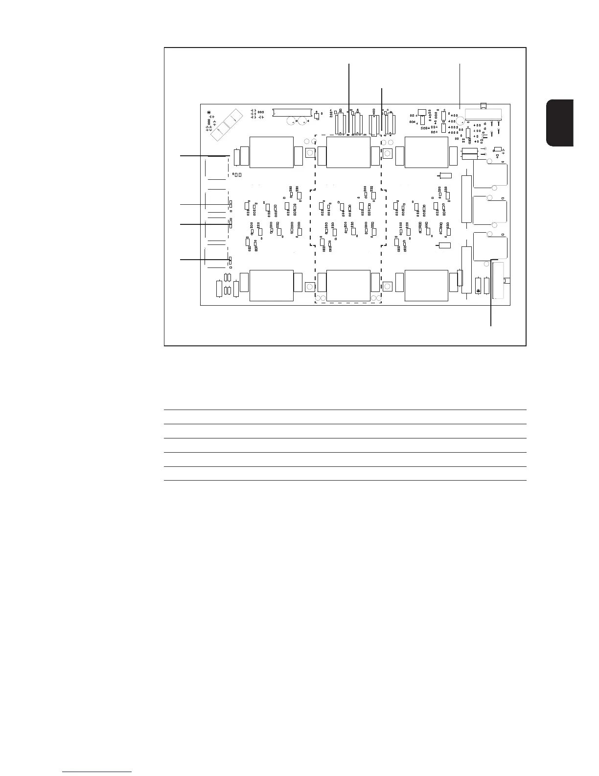
X1
X2
X3
8 transistor module control LEDs
Fig. 20 PC board BPS 53 / 50 >/= V1.4A / 43 / 42 >/= V1.4A
*) ... not on PC board BPS 42 >/= V1.4A and BPS 43
Main switch LED
Intermediate circuit
imbalance LED
LED +15 V primary
High charging relay LED
*)
Function over-
view
- Basic composition: two individual power modules (advantage: power modules can
be switched in series as well as parallel)
- Suitable for a 3 x 400 V AC and 3 x 230 V AC mains supply
- Inputs are electrically isolated by means of isolating transformers and optical
couplers
- Outputs are electrically isolated by means of optical couplers
- 4 parallel transistor modules for BPS 32, BPS 42 >/= V1.4A and BPS 43
6 parallel transistor modules for BPS 42 < V1.4A, BPS 50 and BPS 53
- Each transistor module has a temperature sensor
- Temperature analysed by a PWM signal electrically isolated: the temperature of the
warmest transistor module is transmitted to the UST PC board
- Monitoring of both intermediate circuits for imbalance: a signal is transmitted if
there is any deviation from a permitted range
- Controlling the transistor module via driver stages from the UST PC board
- High charging connection via resistors, time for bridging the resistors by means of
relay is given by UST PC board
- Quick switch-off of power module in the case of a module fault due to permanent
primary current measurement
Technical Data
Input voltage 3 x 230/400 V AC
Input voltage tolerance (+/-15%)
Supply voltage (from NT 24A) 15 V DC primary
Transistor module switching frequency 70 kHz
Intermediate circuit voltage at 400 V AC 2 x 280 V DC

 Loading...