70
Plug layout
(continued)
LED checklist
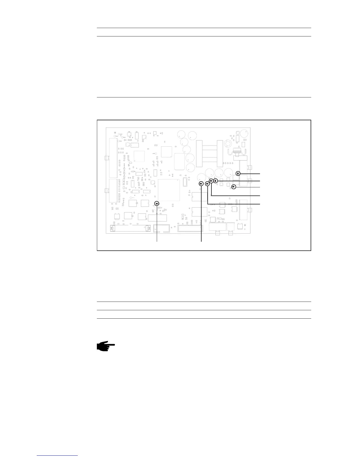
Fig.40 LED indicators on UST PC board
LED +24 V external
LED +24 V internal
LED +5 V (RS 485)
LED -15 V
LED +15 V
LED +5 VLED STAT
- LED STAT flashes when there is no firmware available
Changing UST
PC board
NOTE! Options enabled via „service module“ software are stored on the UST,
and must be re-enabled after changing the UST. Before changing the UST, the
enabled options must be clarified with the customer - the enable codes must
be supplied by the customer.
Measuring points See plug layout.
Measuring points Plug/pin Measuring result command value
Intermediate circuit imbalance X6/26 - X7/8 5 V = OK, 0 V = fault
Pin function
X10 Control for gas solenoid valve and TIG welding torch (optional)
Pin 1 High frequency on/off HF
Pin 2 Gas 1
Pin 3 Gas 2
Pin 4 Crater fill BRT
Pin 5 BRT UP
Pin 6 GND (gun trigger)
Pin 7 GND (HF)
Pin 8 +24 V (Gas 1)
Pin 9 +24 V (Gas 2)
Pin 10 Main current BRT
Pin 11 BRT DOWN
Pin 12 Detection

 Loading...