11
EN
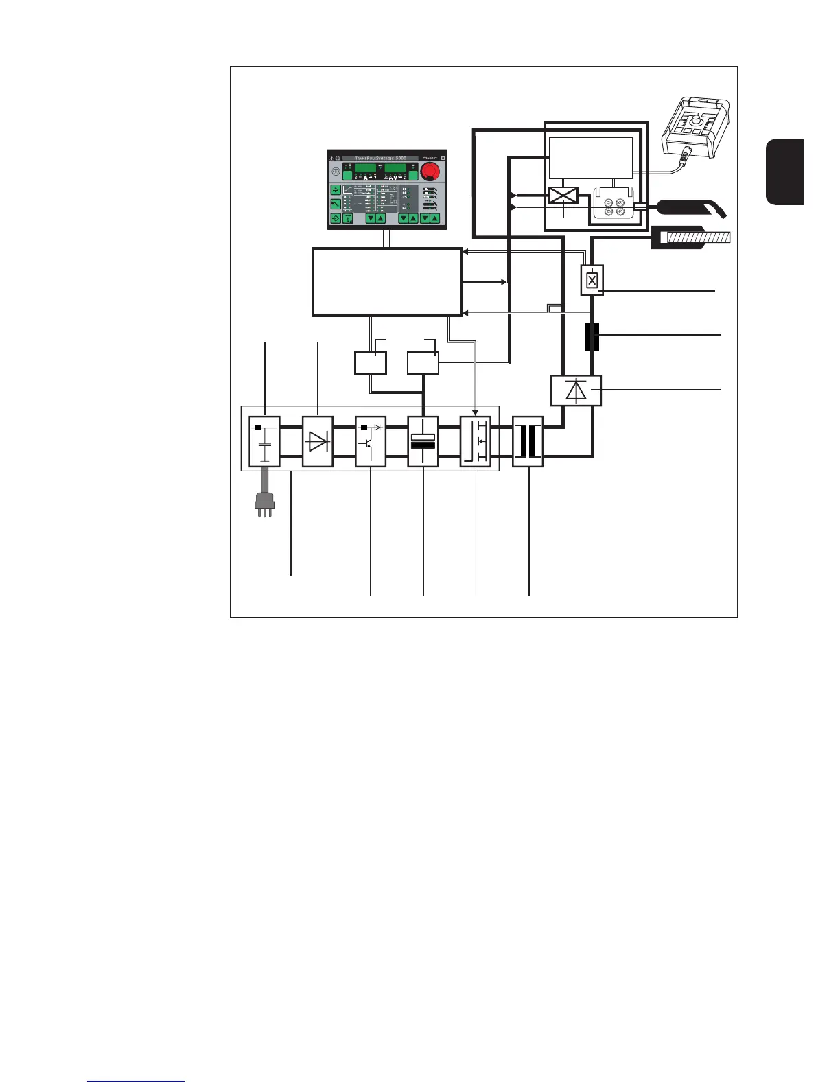
Block diagram
Control and
regulation unit
(1)
(2)
Mains
filter
(3)
Primary
rectifier
(4)
TPS 2700 only: PFC
(Power Factor Control)
(5)
Intermediate circuit
capacitors
(6)
Transistors
(7)
Welding transformer
(8)
Secondary
Rectifer
(9)
Output choke
(10)
Welding current
sensor
Workpiece
Welding torches
Control panel
Remote control
unit
Wire-feed unit
24 V 55 V
Power
supply
55 V
24 V
Primary power module
Local
Net
Local
Net
U
act
I
act
Control
lead
Fig. 2 Block diagram of Trans Synergic 4000/5000 and TransPuls Synergic 2700/3200/4000/5000 power
sources
3 x 400 V
Block diagram
legend
(1) Control and regulation unit:
Controls, regulates and monitors the welding process and all power source func-
tions.
(2) Line filter (EMV):
For attenuation of
- high frequency parts of the mains supply
- reactions on the mains supply
(3) Primary rectifier:
Converts the input voltage (mains voltage) to a rectified intermediate circuit voltage.
(4) PFC (Power Factor Control, TPS 2700 only):
Ensures a sinusoidal current input.
(5) Intermediate circuit capacitors:
Store and smooth the intermediate circuit voltage.
Regulation unit
Valve
Gas
Wire

 Loading...