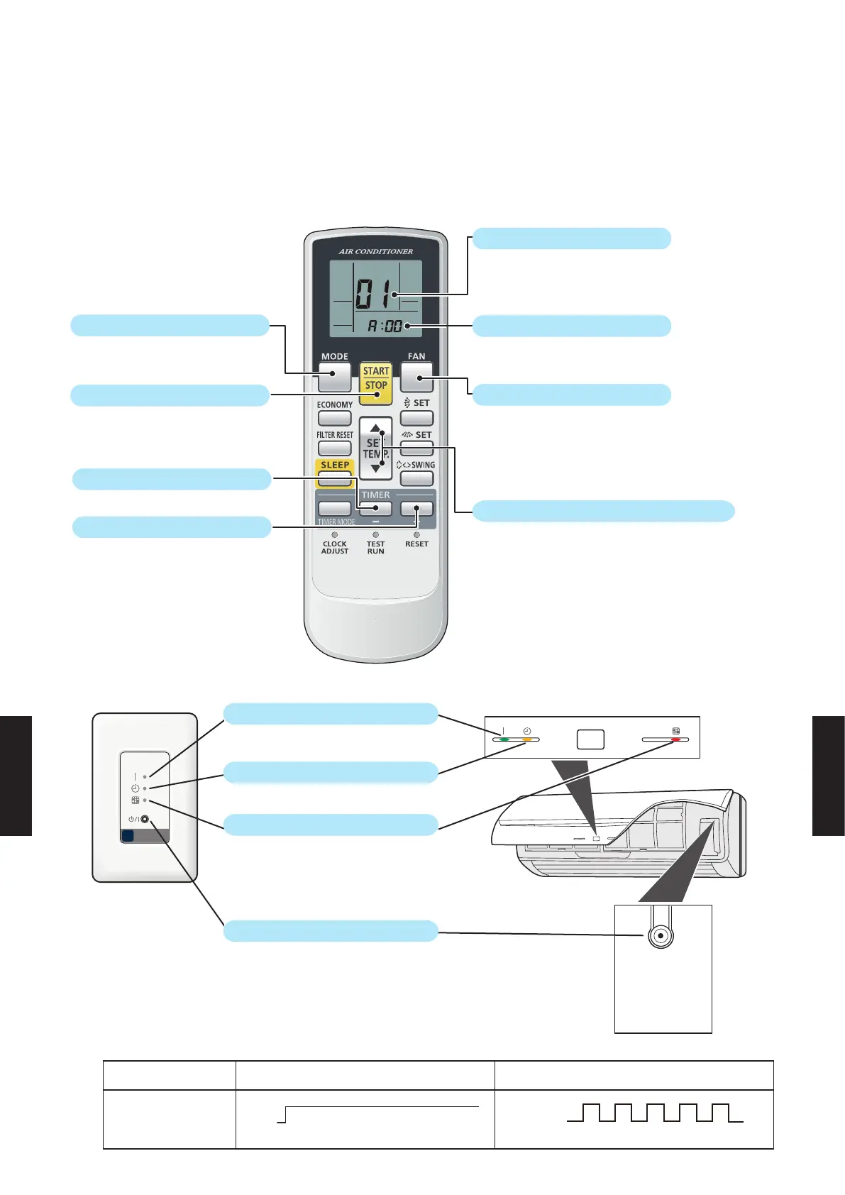
BUTTON NAME AND FUNCTION
● Refer to “1-2" for an outline of the address setting.
● It does not matter whether the refrigerant circuit address or indoor unit address is set first.
(The method shown here sets the indoor unit address first.)
● During address setting mode, indoor unit will not recognize any remote controller operation commands.
●
NOTE:
Address code display is as follows (operation lamp display)
MODE button
START/STOP button
TIMER set (-) button
TIMER set (+) button
SET TEMP. "
p
" and "
q
" button
FAN button
Setting number
Function number
01 --- Indoor unit address
02 --- Refrigerant circuit address
Setting number
* Indoor unit address valid range 00-63
Refrigerant circut address valid range 00-99
Switches between the setting number (bottom line)
and function number (top line)
Increases and decreases the displayed number
- Start the address setting mode
- Changes the address display digits
Transmits address setting
Reconrmation of address setting.
Conrmation of address setting.
Indication of address code
Indication of address data number (the ten’s place)
Indication of address data number (the one’s place)
Long press ----- Switches between the address setting mode and
(3 sec more) the address setting complete mode.
Short press ----- Switches the indicator display
MANUAL
AUTO
OPERATION L AMP
IR RECEIVER UNIT
TIMER LAMP
FILTER L A MP
MANUAL/AUTO button
INDOOR UNIT ADDRESS DISPLAY REFRIGERANT CIRCUIT ADDRESS DISPLAY
OPERATION LAMP
ON
OFF
(Light continuously)
ON
OFF
(Light 1 sec ON / 1 sec OFF)
- (07 - 18) -
FUNCTION
SETTING
FUNCTION
SETTING

 Loading...


