Connection example 2: When the electricity meter is connected
K1 K2 K1 K2
CH1 CH2
TM201
EXTERNAL INPUT
(WHITE)
CN411
(RED)
CN412
CN201
Electricity meter
PCB
PCB
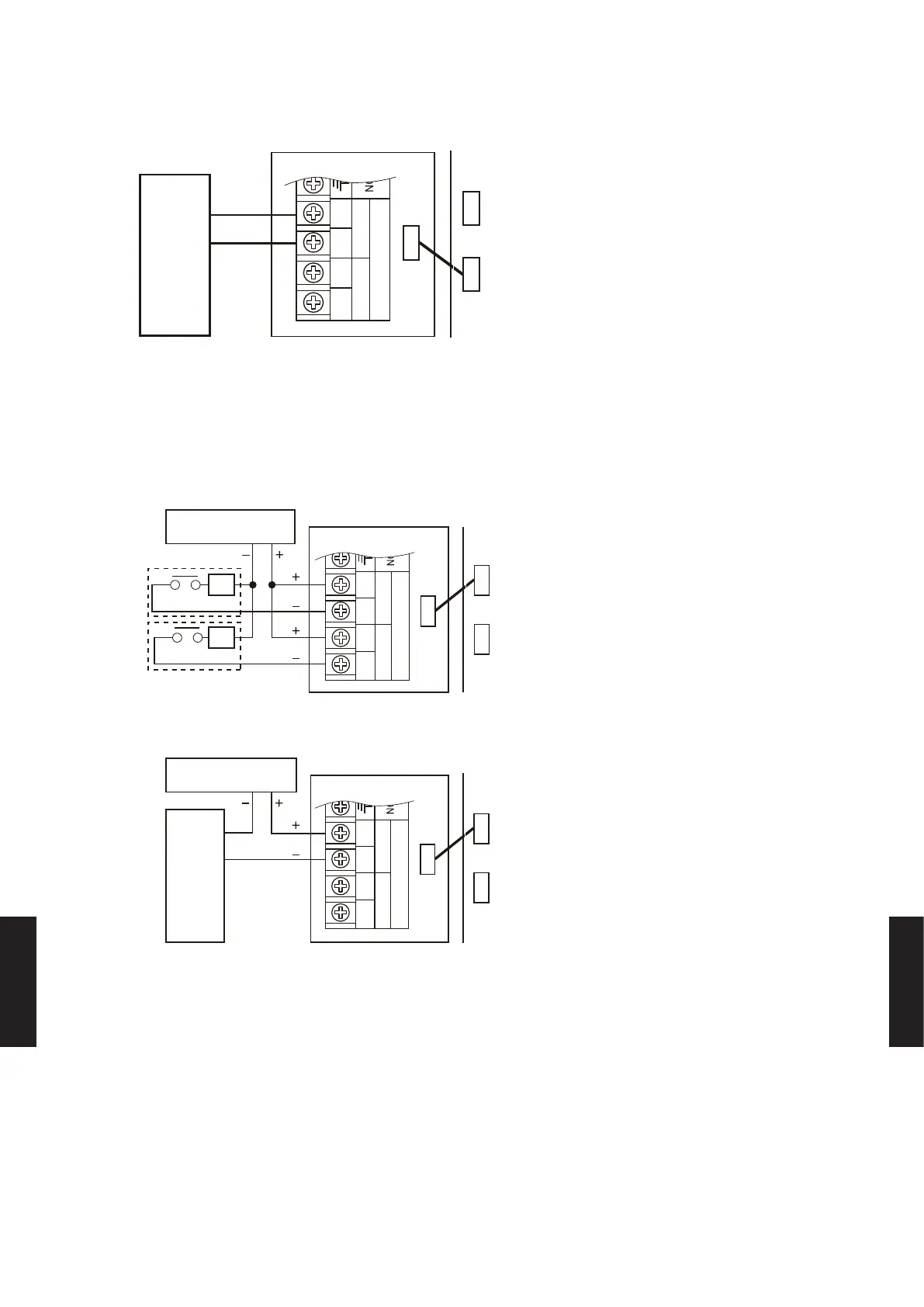
Connect the electricity meter to CH1. In this case, the use of CH2 is prohibited.
z
Apply voltage terminal TM201 (CN412)
When a power supply must be provided at the input device you want to connect, use the Apply
voltage terminal TM201 (CN412).
Connection example 1: When the switch is connected
CN201
*4
*3
*2
*4
K1 K2 K1 K2
CH1 CH2
TM201
DC power
supply 12-24 V
TUPNI LANRETXE
PCB
PCB
(RED)
CN412
(WHITE)
CN411
Connection example 2: When the electricity meter is connected
CN201
*2
K1 K2 K1 K2
CH1 CH2
TM201
*3
DC power
supply 12-24 V
TUPNI LANRETXE
Electricity meter
PCB
PCB
(RED)
CN412
(WHITE)
CN411
*2: Make the power supply DC 12 to 24 V. Select a power supply capacity with an ample
surplus for the connected load.
*3: Do not impress a voltage exceeding 24 V across K1-K2.
*4: The allowable current is DC 10 mA or less. (Recommended DC 5 mA) Provide a load
resistance such that the current becomes DC 10 mA or less. Select very low current use
contacts (usable at DC 12 V, DC 1 mA or less). A twisted pair cable 0.33 mm
2
(22AWG)
should be used. Maximum length of cable is 25 m (82 ft).
- (08 - 49) -
EXTERNAL INPUT
& OUTPUT
EXTERNAL INPUT
& OUTPUT

 Loading...


