¢
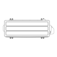
Component location of PCB
Modbus Network
connection port
VRF Network
connection port
Modbus
terminal
resister switch (SET7-4)
VRF terminal resister
switch (SET2-1)
Test run switch (SET2-3)
Scan switch (SET2-4)
Modbus
communication
baud rate switch (SET6-4)
Modbus
communication
parity switch (SET6-3)
Modbus communication
stop bit switch (SET6-2)
Modbus
slave address
switch (SET4/SET5)
Convertor address
switch (SET1)
USB cable connector
¢
E
lectrical wiring
Modbus cable
L (L1)
N (L2)
General purpose building
control computer
(Modbus Device)
Indoor unit
Transmission cable
Outdoor unit
Master or Slave
O
utdoor unit
Power supply
cable
Transmission cable
to Modbus network
Transmission cable
to VRF network
Modbus convertor
1Ø 50/60 Hz
208-240 V
(Disconnect switch)
Switch
Fuse (2 A)
Power supply cable
¢ F
unctions
• Indoor unit control
–
Individual control
Commands from Modbus network are sent to the respective indoor units.
(Modbus network → respective indoor units of VRF network)
– Batch control
Commands from Modbus network are sent to all indoor units connected to VRF network.
(Modbus network → All indoor units of VRF network)
• Indoor unit status monitoring
Indoor unit status is communicated to the Modbus network in the form of Lon network variables.
(Modbus network ← All indoor units of VRF network)
3-4. Modbus convertor for VRF (UTY-VMGX) - (05-131) - 3. Adaptor/Convertor units
CONTROL
SYSTEM
CONTROL
SYSTEM
 Loading...