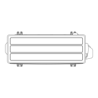
3-3. Header
Total cooling capacity of indoor
units (
x) (Btu/h)
3 to 6 Branches 3 to 8 Branches
x < 96,500 UTR-H0906L UTR-H0908L
96,500 ≤ x UTR-H1806L UTR-H1808L
NOTE: When separate into 2 branches, use a Separation tube instead.
¢
I
nstallation
1. Connecting the connection pipes from the indoor units.
Gas pipe
Outdoor
unit side
Liquid pipe
Always have at least one
indoor unit connected to
the port furthest (opposite)
the outdoor unit side.
You can connect the indoor
unit to any branch.
Outdoor
unit side
You can connect the indoor
unit to any branch.
Always have at least one
indoor unit connected to
the port furthest (opposite)
the outdoor unit side.
2. Use a pipe cutter to cut at the location that matches the piping size or use expanders as neces-
sary.
Joint pipe
C
onne
c
tion
s
Field pipe
Expander
Cut in the center of
the connections
3. Attach a plugging pipe provided if there is no piping connected at the Headers.
Connection pipes
Closed pipes
4. Connecting pipe locally purchased from outdoor unit, cut the pipe end to connect the pipe and
close the opposite end.
Liquid pipe
Cut 1 in (25 mm)
Field piping
Pipe cutter
3-3. Header - (06-45) - 3. Piping connection
SYSTEM
DESIGN
SYSTEM
DESIGN
 Loading...