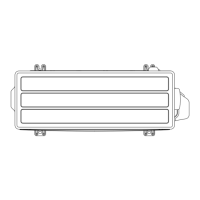
2-20. Modbus convertor for VRF
¢ Switch location
Set the rotary switch (SET1) and DIP switches (SET2, 4, 5, 6, 7) on the PCB.
¢ Rotary switch setting
• SET1:
Modbus convertor remote controller address setting
Refrigerant circuit
address
(Example)
Rotary switch setting
SET1 (x10)
(10 digit)
SET1 (x1)
(1 digit)
01
0 1
15
1 5
NOTES:
•
Factory setting: 00
• Setting range: 00 to 15 (Arbitrary numbers can be set.)
• When the rotary switch is set to 16 or more, the remote controller address of the convertor
is 15.
• The sum total of the Touch panel controller, Central remote controller, Network convertor for
Group remote controller, Modbus convertor, and Network convertor for LonWorks is a maxi-
mum of 16.
• For Touch panel controller, Central remote controller, Network convertor for Group remote
controller, Modbus convertor, and Network convertor for LonWorks connected in same VRF
network system, set an exclusive address on each device.
• This convertor is connectable a maximum of 9 in 1 VRF network system.
2-20. Modbus convertor for VRF - (07-121) - 2. Function settings
FUNCTION
SETTINGS
FUNCTION
SETTINGS
 Loading...