• Filter mode setting
Set the filter mode to suppress an increase of the amount of communication information in the
Heat recovery system.
– Filter mode is turned on by inserting the accessory connecting wire at the CN4 connector on the
PCB.
– When the filter mode setting is changed, turn the power off once. Otherwise, the setting will not
be recognized.
CN4
Connecting wire (Accessory)
Body
PCB
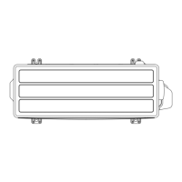
¢ D
imensions
Unit: in (mm)
For dust proof bushing
Ø1-1/8 (28)
3-1/2 (89.5) 3-1/2 (89.5)
For dust proof bushing
Ø1-1/8 (28)
1-1/8 (29)
2-Ø3/16 (5)
For M4 × 20 mm
screws
Hole pitch
3-3/4 (95)
Hole pitch
3-3/4 (95)
8-5/16 (211)
2-5/8 (67)
4-Ø3/16 (5)
For M4 × 20 mm screws
Ø7/8 (22) For conduit
9-1/2 (241.6)
10-11/16 (272) Hole pitch
11-5/16 (288)
3-8. Signal amplifier (UTY-VSGXZ1) - (05-158) - 3. Adaptor/Convertor units
CONTROL
SYSTEM
CONTROL
SYSTEM
 Loading...