¢
Refrigerant system examples
NOTE: For cooling capacity range of connectable indoor units, refer to "Refrigerant system" on
page 06-1.
Example 1 (OK)
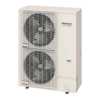
Outdoor unit
I
ndoor unit 1 Indoor unit 2
Capacity ratio 83%
Model name
Cooling
capacity
Total
capacity
Connectable
indoor unit
capacity
Judge
Min. Max.
(kBtu/h)
Outdoor unit AOU72RLAVL 72 72
(2) 50%
36
(3) 150%
108
(2) ≤ (1) ≤ (3)
36 < 60 < 108 → OK
Indoor unit 1 AUUB30TLAV2 30
(1) 60
Indoor unit 2 AUUB30TLAV2 30
Example 2 (OK)
Outdoor unit
I
ndoor unit 1 Indoor unit 2 Indoor unit 3
Capacity ratio 130%
Model name
Cooling
capacity
Total
capacity
Connectable
indoor unit
capacity
Judge
Min. Max.
(kBtu/h)
Outdoor unit AOU72RLAVL 72 72
(2) 50%
36
(3) 150%
108
(2) ≤ (1) ≤ (3)
36 < 84 < 108 → OK
Indoor unit 1 AUUB30TLAV2 30
(1) 84Indoor unit 2 AUUB30TLAV2 30
Indoor unit 2 AUUA24TLAV2 24
1-1. Refrigerant system - (06-2) - 1. System design
SYSTEM
DESIGN
SYSTEM
DESIGN
 Loading...