¢
Example 2
a
b1 b2
b3
HD1
Total cooling capacity of indoor units connected
downwards to the pipe
Indoor
unit
Indoor
unit
Indoor
unit
1
18 kBtu/h
2
30 kBtu/h
3
30 kBtu/h
18 kBtu/h 30 kBtu/h 30 kBtu/h
Outdoor
unit
78 kBtu/h
• System configuration
Indoor unit Model name Capacity (kBtu/h)
1 AUUB18TLAV2 18.0
2 AUUB30TLAV2 30.0
3 AUUB30TLAV2 30.0
Total capacity 78.0
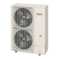
Outdoor unit Model name Capacity (kBtu/h)
1 AOU96RLAVL 96.0
Total capacity 96.0
• Capacity ratio
(Total capacity of indoor unit)/(Total capacity of outdoor unit)
= 78.0 / 96.0 = 81.25% (Within 50% to 150%)
• Selection of
Separation tube and Header
Branch kit no. Model name Quantity
HD1 UTR-H0906L 1
• Selection of pipe size
Pipe no.
Pipe diameter: in (mm)
Length example
ft (m)
Liquid pipe Gas pipe
a Ø1/2 (12.70) Ø7/8 (22.22) 232 (71)*
b1 Ø1/4 (6.35) Ø1/2 (12.70) 19 (6)
b2 Ø3/8 (9.52) Ø5/8 (15.88) 19 (6)
b3 Ø3/8 (9.52) Ø5/8 (15.88) 22 (7)
*: When the length of the pipe between outdoor unit and the first separation tube or header is
greater than 229 ft (70 m), liquid pipe must be size up from 3/8 in (9.52 mm) to 1/2 in (12.70 mm).
For details, refer to "Pipe size selection" on page 06-22.
2-6. Piping design example - (06-31) - 2. Piping design
SYSTEM
DESIGN
SYSTEM
DESIGN
 Loading...