¢
Restriction when install
Be sure following restriction.
• Installation angle
Install the Header so that it branches horizontally.
Gas pipe
OK Prohibited Prohibited
Liquid pipe
Horizontal
Horizontal
Use a level to make sure that the Header is positioned as shown in following figure, and then sure
it in place.
A
H1
α1
β1
B
H
2
Gas pipe
V
iew from A
View from B
H1 = 0 to 3/8 in (0 to 10 mm)
α1: 0° to 1°
β1: -10° to +10°
H2 = 0 to 3/8 in (0 to 10 mm)
α2: 0° to 1°
β2: -10° to +10°
Liquid pipe
Outdoor
unit side
Horizontal
line
Vertical line
Brazing point
Outdoor
unit side
Horizontal
line
β
2
Horizontal
line
B
razing
point
α2
• Straight pipe length
A straight pipe (minimum length
2 ft [0.5 m]) before Header is necessary in order to separate the
refrigerant exactly.
Main pipe
2 ft (0.5 m)
or more
To indoor unit
To indoor unit
To indoor unit
2 ft (0.5 m)
or more
¢
H
eat insulation installation
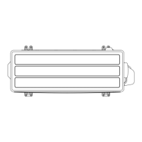
After brazing the piping, attach heat insulation.
1.
Remove the protective paper for the tape on the heat insulation for the header and attach it.
Tighten by using binders at five locations.
2. Cover the plugging pipe with heat insulation and seal with tape.
Plugging pipe
H
eat insulation
for plugging pipe
Heat insulation
for header
Tape (Locally purchased)
Heat insulation
for plugging pipe
3-3. Header - (06-47) - 3. Piping connection
SYSTEM
DESIGN
SYSTEM
DESIGN
 Loading...