EasyManuals Logo

Fujitsu PRIMERGY RX1330 M4 Upgrade And Maintenance Manual

Fujitsu PRIMERGY RX1330 M4
403 pages
To Next Page IconTo Next Page
To Previous Page IconTo Previous Page
Page #202 background imageLoading...
Page #202 background image
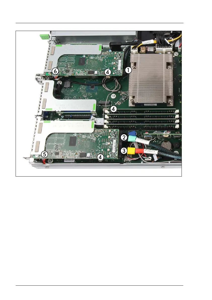
Figure 118: Example - PRAID EP5x0i in riser module 1 and riser module 3
â–
Connect the following cables:
1 SAS/SATA cable, is routed to top side and left side 4x 2.5-inch HDD
backplane
2 Oculink cable (green/black), is routed to bottom side and right side 4x
2.5-inch PCIe SSD backplane
3 Oculink cable (yellow/red), is routed to bottom side and right side 4x
2.5-inch PCIe SSD backplane
4 HDD LED cable to system board connector "HDD LED"
5 If applicable, FBU cable, is routed to bottom side
6 If applicable, FBU cable, is routed to top side
Expansion cards and backup units
202 Upgrade and Maintenance Manual RX1330 M4

Table of Contents

Other manuals for Fujitsu PRIMERGY RX1330 M4

Questions and Answers:

Question and Answer IconNeed help?

Do you have a question about the Fujitsu PRIMERGY RX1330 M4 and is the answer not in the manual?

Fujitsu PRIMERGY RX1330 M4 Specifications

General IconGeneral
ChipsetIntel C246
ProcessorIntel Pentium, Intel Celeron
Memory TypeDDR4
MemoryUp to 64 GB
Memory Slots4 DIMM slots
Drive Bays4 x 3.5-inch or 8 x 2.5-inch
Network2x 1GbE onboard, optional additional NICs
Power Supply450W
Form Factor1U
RAID Controlleroptional SAS RAID controller

Related product manuals