174
<
Data
>
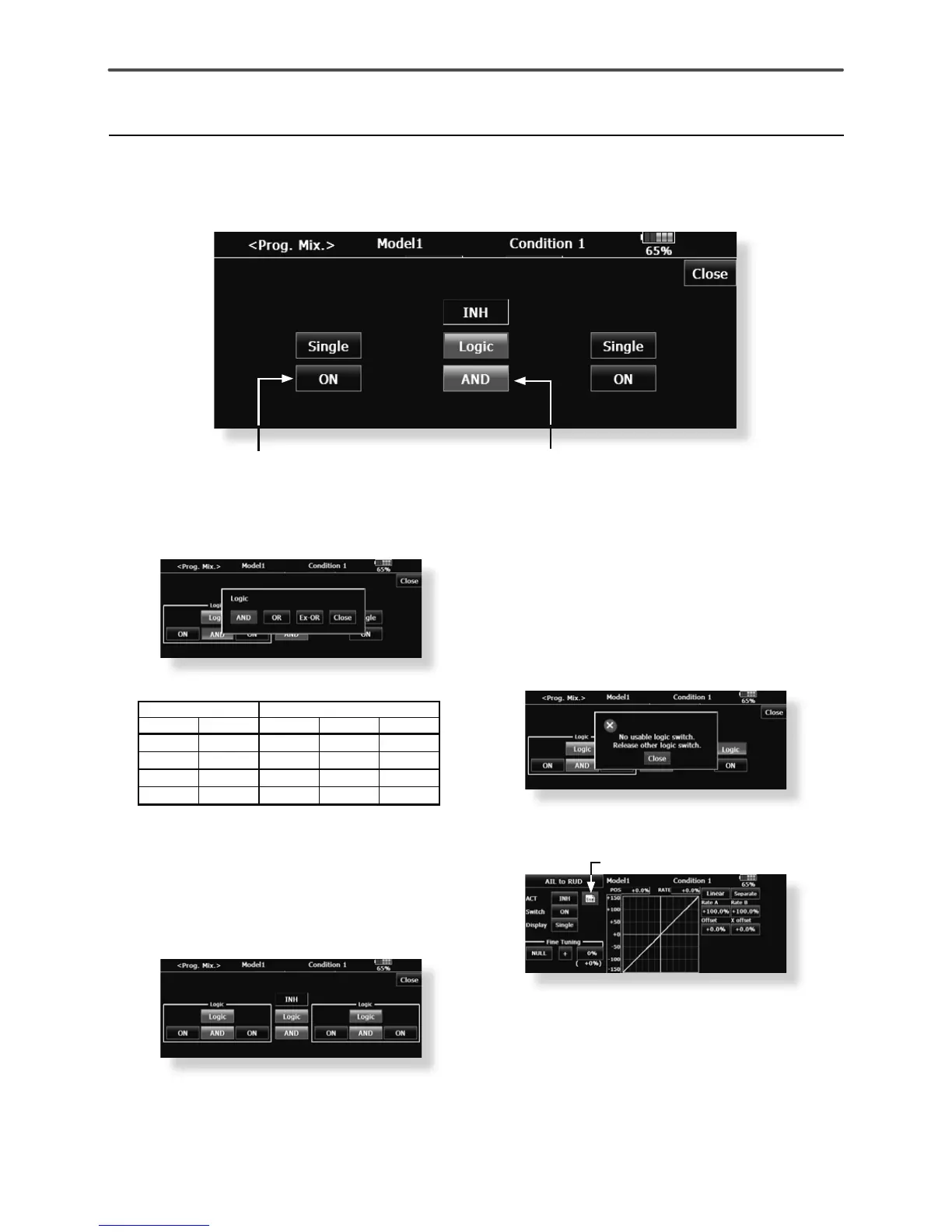
Logic switch
In the Logic screen, the switch selection buttons appear on both the left and right side of the display.
(Logic switch setting screen)
ŏ/RJLFPRGHEXWWRQ
1.The logic selection dialogue appears when
you push the logic mode button. The 3 types
RIORJLFHLWKHU$1'25RU(;25FDQEH
selected.
Logic combination table:
SWITCH /2*,&
SW1 SW2 $1' 25 ([25
off off off off off
off on off on on
on off off on on
on on on on off
2. The left and right side of the switch mode
can be set to the logic switch mode as well.
In this case, a maximum of 4 switches can
be assigned to the logic switch. The left and
ULJKWORJLFDUHFDOXODWHGÀUVWWKHQWKHFHQWHU
RIWKHORJLFLVFDOFXODWHG)LQDOO\VZLWFKRQ
off status determined by the 4 switches'
combination.
In the above case, the two switches in the
OHIWDUHFDOFXODWHGE\$1'ORJLF1H[WWKH
two switches in the right are calculated as
VDPHZD\)LQDOO\WKHÀUVWFDVHDQGQGFDVH
DUHFDOFXODWHGE\25ORJLF
Caution:
1. The maximum number of the logic switch is
IRUWKHÁLJKWFRQGLWLRQVHOHFWDQGIRUWKH
PL[LQJRQRIIVHOHFWLRQRQHDFKÁLJKWFRQGLWLRQ
The error message will appear when the
exceeded logic switch is going to be selected.
,QWKLVFDVHGHOHWHWKHXQXVHGORJLFVZLWFKÀUVW
then select the new logic switch.
2. The mixing on/off switch modes are
automatically assigned by single mode, not
supported the group mode.
Assigned to single mode
ŏ6ZLWFKVHOHFWLRQEXWWRQ
 Loading...