44
<
Model Basic Setting Procedure
>
&RQÀUPWKDWWKHUDWHRIWKHVORZHVWSRVLWLRQRI
WKHVWLFNLVLQLWLDOVHWWLQJ
%HVXUHWKDWZKHQVHWWRKLJKVLGHWKHFXUYHRI
DQ\FRQGLWLRQGRHVQRWH[FHHG
Example of pitch curve setting:
1. Call the pitch curve of each condition with
the condition select switch.
*Pitch curve graph display can be switched to pitch angle direct
reading display.
$3LWFKFXUYH1RUPDO
Make the pitch at hovering approximately +5
º
~6
º
.
Set the pitch at hovering with the stick position at
WKHSRLQWDVWKHVWDQGDUG
*Stability at hovering may be connected to the throttle curve.
Adjustment is easy by using the hovering throttle function and
hovering pitch function together.
%3LWFKFXUYH,GOHXS
The idle up 1 pitch curve function creates a curve
PDWFKHGWRDLUERUQHÁLJKW
Set to -7
º
a
º
as standard.
&3LWFKFXUYH,GOHXS
The high side pitch setting is less than idle up 1.
The standard is +8
º
.
D. Pitch curve (Hold)
$WDXWRURWDWLRQXVHWKHPD[LPXPSLWFKDWERWK
the high and low sides.
[Pitch angle setting example]
7KURWWOHKROG
º
a
º
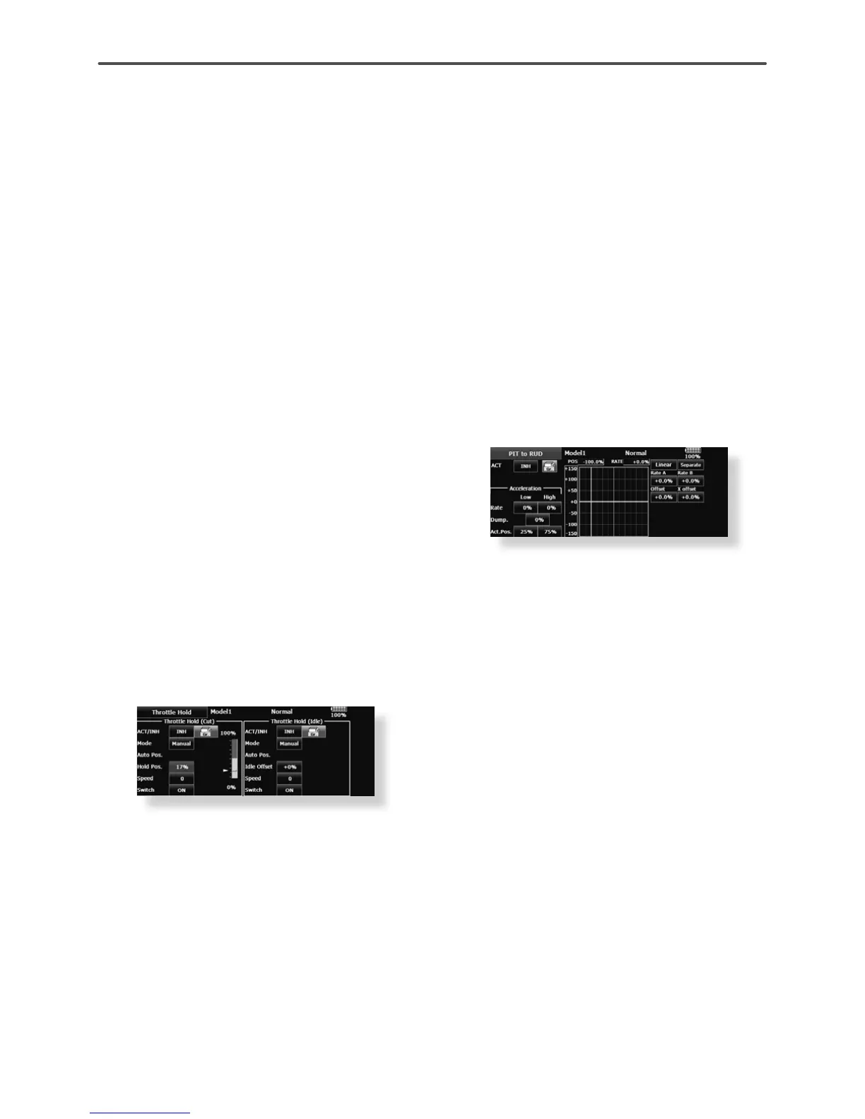
6. Throttle hold setting
Call the Throttle Hold function from the Model
Menu and switch to the throttle hold condition with
the condition select switch.
Note: $WLQLWLDOVHWWLQJWKHVHWWLQJPRGHLVWKH
group mode. Since this function is not used at other
conditions, switch to the single mode before setting.
ŏ6HWWLQJWRWKHVWDWHZKLFKDFWLYDWHVWKHIXQFWLRQ
The throttle hold function allows setting for throttle cut
DQGVZLWFKLQJRIWKHIXQFWLRQÀ[HGDWWKHLGOHSRVLWLRQ
by switch for training. Either one or both functions
can be performed.
ŏ+ROGSRVLWLRQVHWWLQJ
This function sets the servo operation position at
throttle hold. (Throttle cut and idle positions)
ŏ2WKHUVHWWLQJV
When you want to link operation with stick
PDQLSXODWLRQWKH$XWRPRGHFDQEHVHW
When you want to adjust the servo speed, adjust
[Speed].
3LWFKWR58'PL[LQJVHWWLQJ
Use this function when you want to suppress
the torque generated by the changes in the pitch
and speed of the main rotor during pitch operation.
Adjust it so that the nose does not swing in the
rudder direction. However, when using a heading
hold gyro like those shown below, do not use Pitch
to RUD mixing.
Note:KHQXVLQJD)XWDED*<VHULHVJ\URRURWKHU
KHDGLQJKROGJ\URWKLV3LWFKWR58'PL[LQJVKRXOG
not be used. The reaction torque is corrected at
WKHJ\URVLGH:KHQRSHUDWLQJWKHJ\URLQWKH$9&6
mode, the mixed signal will cause neutral deviation
symptoms and the gyro will not operate normally.
Call the Pitch to RUD mixing function from the
Model Menu, and set the curve for each condition.
(At initial setting, this function is in the "INH" state.
To use it, set it to the "ON" state.)
(17 points curve)
Curve setting of up to 17 points is possible.
However, in the following setting example, a simple
curve can be adjusted by using the [Linear] curve
type.
Note:$WLQLWLDOVHWWLQJWKHVHWWLQJPRGHLVWKHJURXS
PRGH,QWKLVPRGHWKHVDPHFRQWHQWVDUHVHWDWLQ
all conditions. When you want to set the selected
condition only, switch to the single mode.
6HWWLQJH[DPSOH!
Call the mixing curve of each condition with the
condition select switch.
The throttle hold curve is used when performing auto
rotation dives.
 Loading...