Garmin G1000 Pilot’s Guide for the Socata TBM 850/900
190-00709-05 Rev. D
522
AUTOMATIC FLIGHT CONTROL SYSTEM
7.4 LATERAL MODES
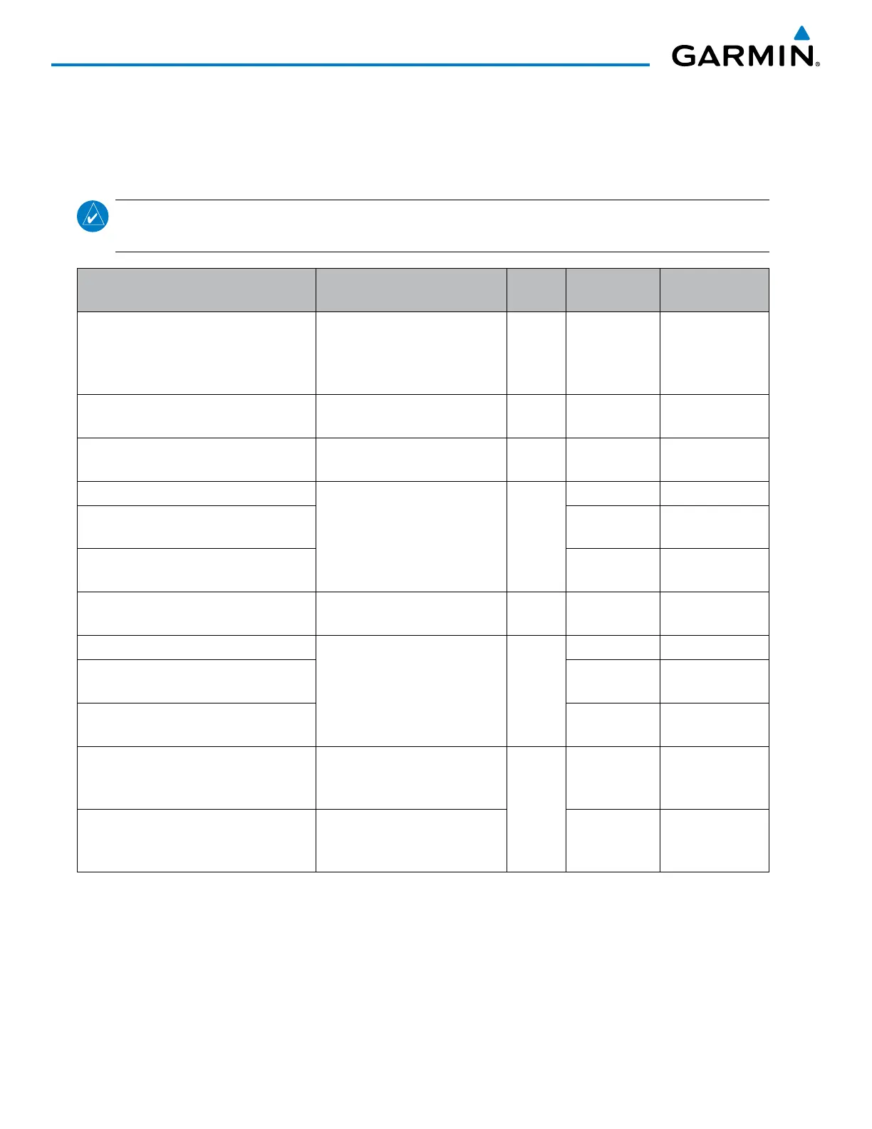
The following table relates each AFCS lateral mode to its respective control and annunciation. Refer to the
vertical modes section for information regarding Takeoff and Go Around modes.
NOTE: The AFCS may generate a lower bank angle than the maximum roll command limit in degrees
indicated in table 7-3 by the amount needed to produce a turn rate equal to or less than standard rate.
Lateral Mode Description Control Annunciation
Maximum Roll
Command Limit
Roll Hold
Holds the current aircraft roll
attitude or rolls the wings level,
depending on the commanded
bank angle
(default) ROL 25°
Low Bank
Limits the maximum commanded
roll angle
BANK
Key
* 15°
Heading Select **
Captures and tracks the Selected
Heading
HDG
Key
HDG 25°
Navigation, GPS **
Captures and tracks the selected
navigation source (GPS, VOR,
LOC)
NAV
Key
GPS 25°
Navigation, VOR Enroute Capture/Track ** VOR
25° Capture
10° Track
Navigation, LOC Capture/Track
(No Glideslope)
LOC
25° Capture
10° Track
Backcourse Capture/Track
Captures and tracks a localizer
signal for backcourse approaches
BC Key BC
25° Capture
10° Track
Approach, GPS
Captures and tracks the selected
navigation source (GPS, VOR,
LOC)
APR Key
GPS 25°
Approach, VOR Capture/Track VAPP
25° Capture
10° Track
Approach, LOC Capture/Track
(Glideslope Mode automatically armed)
LOC
25° Capture
10° Track
Takeoff
Commands a constant pitch angle
and wings level on the ground in
preparation for takeoff
GA
Switch
TO Wings Level
Go Around
Disengages the autopilot and
commands a constant pitch angle
and wings level in the air
GA Wings Level
* No annunciation appears in the AFCS Status Box. The acceptable bank angle range is indicated in green along the Roll
Scale of the Attitude Indicator.
** The Heading, Navigation GPS and Navigation VOR mode maximum roll command limit will be limited to the Low Bank
mode value if it is engaged.
Table 7-3 Flight Director Lateral Modes
The CWS Button does not change lateral references for Heading Select, Navigation, Backcourse, or Approach
Mode. The autopilot guides the aircraft back to the Selected Heading/Course upon release of the CWS Button.

 Loading...


