190-00709-05 Rev. D
Garmin G1000 Pilot’s Guide for the Socata TBM 850/900
63
FLIGHT INSTRUMENTS
VERTICAL SPEED INDICATOR (VSI)
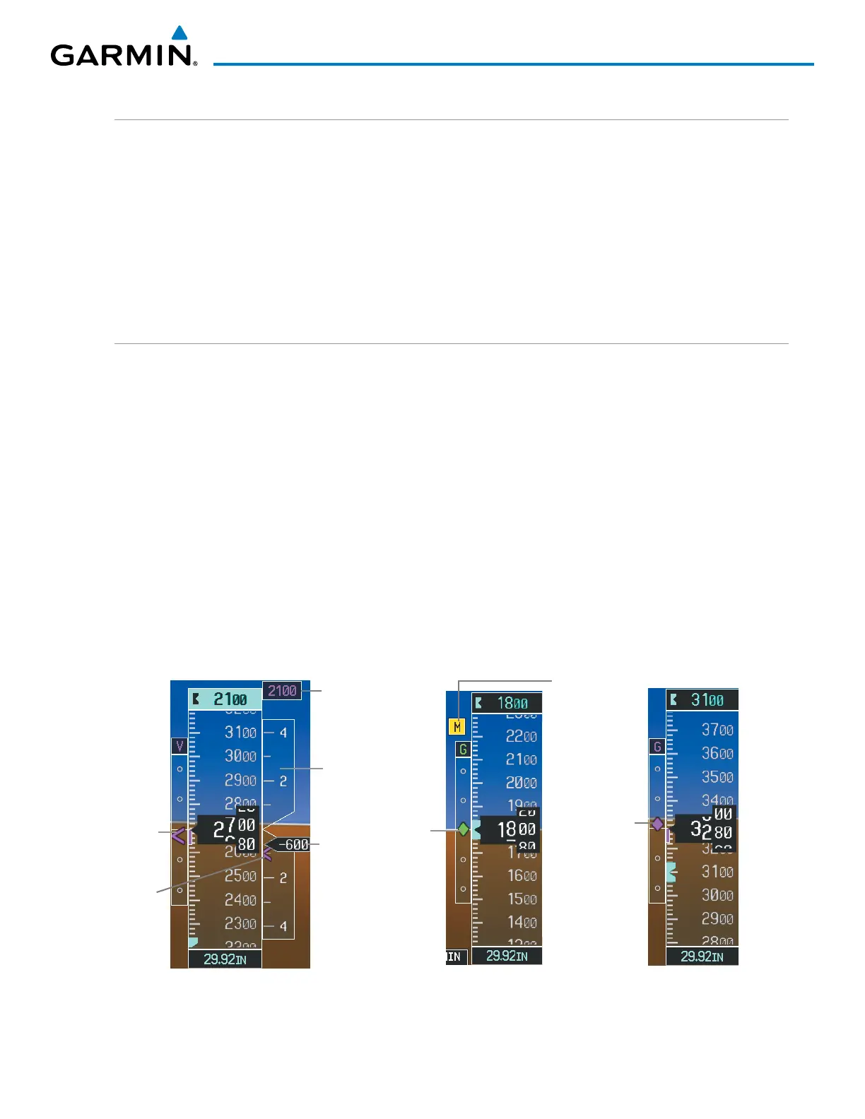
The Vertical Speed Indicator (VSI) displays the aircraft vertical speed on a fixed scale with labels at 2000 and
4000 fpm and minor tick marks every 1000 fpm (Figure 2-13). Digits appear in the pointer when the climb or
descent rate is greater than 100 fpm. If the rate of ascent/descent exceeds 4000 fpm, the pointer appears at the
edge of the tape and the rate appears inside the pointer.
A magenta chevron is displayed on the VSI as the Required Vertical Speed for reaching a VNV Target Altitude
once the “TOD [Top of Descent] within 1 minute” alert has been generated. See the Flight Management
and AFCS sections for details on VNV features, and refer to Section 2.2, Supplemental Flight Data, for more
information about VNV indications on the PFD.
VERTICAL DEVIATION
The Vertical Deviation Indicator (VDI) is a magenta chevron to indicate the baro-VNV vertical deviation when
Vertical Navigation (VNV) is being used. The VDI (Figure 2-13) appears in conjunction with the “TOD within
1 minute” alert. Full-scale deflection (two dots) is 1000 feet. The VDI is removed from the display if vertical
deviation becomes invalid. See the Flight Management and AFCS sections for details on VNV features, and refer
to Section 2.2, Supplemental Flight Data, for more information about VNV indications on the PFD.
The Glideslope Indicator (Figure 2-14) appears to the left of the Altimeter whenever an ILS frequency is tuned
in the active NAV field and the aircraft heading and selected course are within 107˚. A green diamond acts as
the Glideslope Indicator, like a glideslope needle on a conventional indicator. If a localizer frequency is tuned
and there is no glideslope, “NO GS” is annunciated in place of the diamond.
The glidepath is analogous to the glideslope for GPS approach service levels supporting SBAS vertical guidance
(LNAV+V, LNAV/VNAV, LP, LPV, LP+V). When an approach of one of these service levels is loaded into the flight
plan and GPS is the selected navigation source, the Glidepath Indicator (Figure 2-15) appears as a magenta
diamond when the aircraft reaches a point prior to the FAF. If the approach type changes past the final approach
fix (FAF), “NO GP” is displayed in place of the diamond.
Glidepath
Indicator
Figure 2-15 Glidepath Indicator
Glideslope
Indicator
Marker
Beacon
Annunciation
Figure 2-14 Glideslope Indicator
Vertical
Speed
Indicator
Vertical
Speed
Pointer
VNV
Target
Altitude
Vertical
Deviation
Indicator
Figure 2-13 Vertical Speed and
Deviation Indicators (VSI and VDI)
Required
Vertical
Speed
Indicator

 Loading...


