Installation 5.5 Installing Communication Interfaces
Page 60 MDE-5411A ForeHB Islander Prime Installation Manual · October 2018
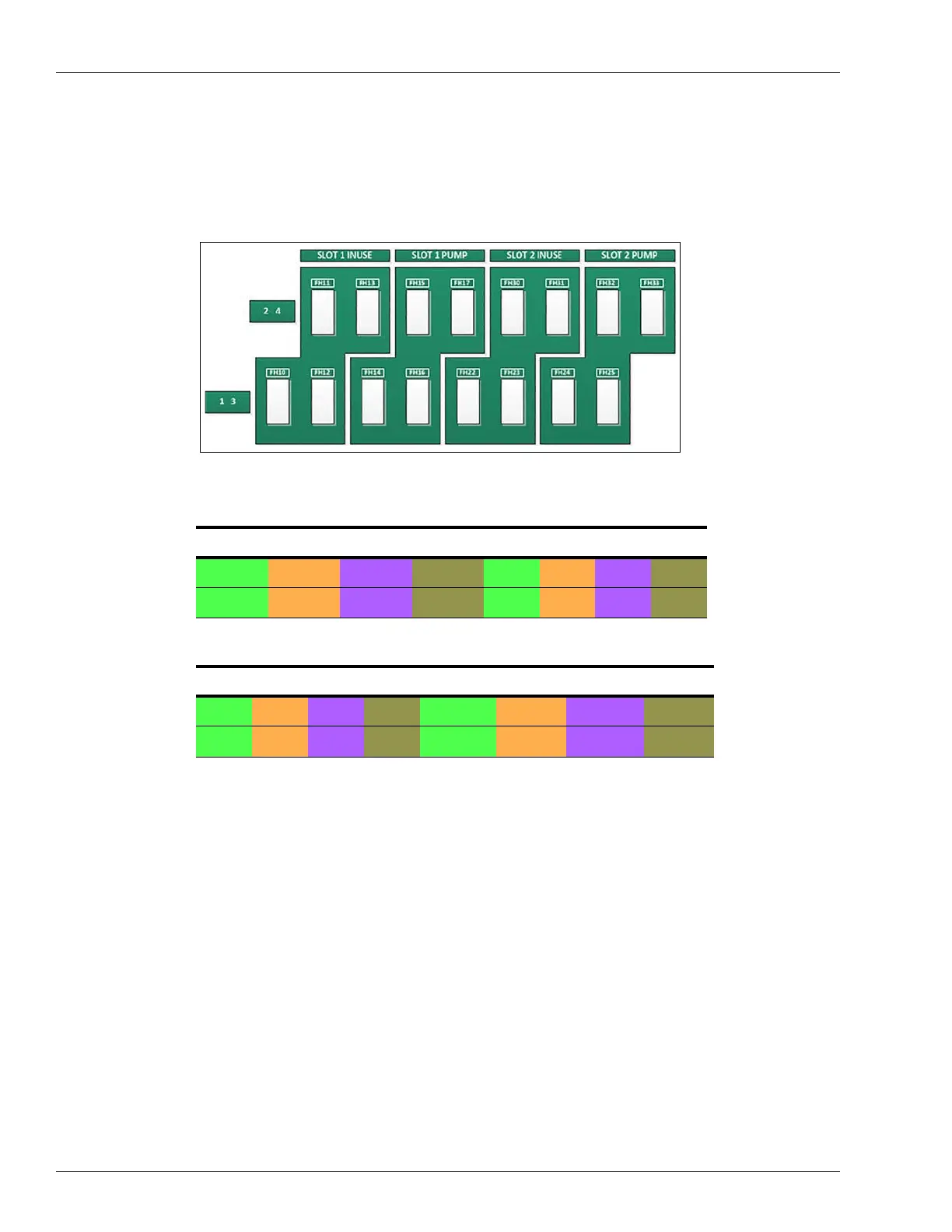
5.5.3.5 Fuses
Mechanical pumps are supplied with power via fuses located below the pump slots
(see Figure 48, Table 12, Table 13):
Figure 48: MPI-C Fuses Diagram
Table 12:
In Use Pump
INUSE1_A INUSE2_A INUSE3_A INUSE4_A LINE1 LINE2 LINE3 LINE4
INUSE1_B INUSE2_B INUSE3_B INUSE4_B LOAD1 LOAD2 LOAD3 LOAD4
MPI-C Fuses Slot #1- In Use/Pump
Table 13:
In Use Pump
LINE1 LINE2 LINE3 LINE4 INUSE1_A INUSE2_A INUSE3_A INUSE4_A
LOAD1 LOAD2 LOAD3 LOAD4 INUSE1_B INUSE2_B INUSE3_B INUSE4_B
MPI-C Fuses Slot #2 - Pump/In Use
5.5.4 Pulser Connections
The following describes the required wiring connections between the pulser in the mechanical
pump and Islander Prime. The system can accept many types of pulsers; contact Gasboy for
more information. There are two types of pulser:
• Electronic pulser
• Mechanical pulser
Connect Islander Prime to the pulser in ac
cordance to its characteristics.
Note: Pulsers should be installed in accordance with the pulser manufactur
er's instructions.
Some pulsers do not have a barrier; in that case, you must add a pulser barrier.
Barriers are not provided with Islander Prime.