Installation 5.5 Installing Communication Interfaces
Page 64 MDE-5411A ForeHB Islander Prime Installation Manual · October 2018
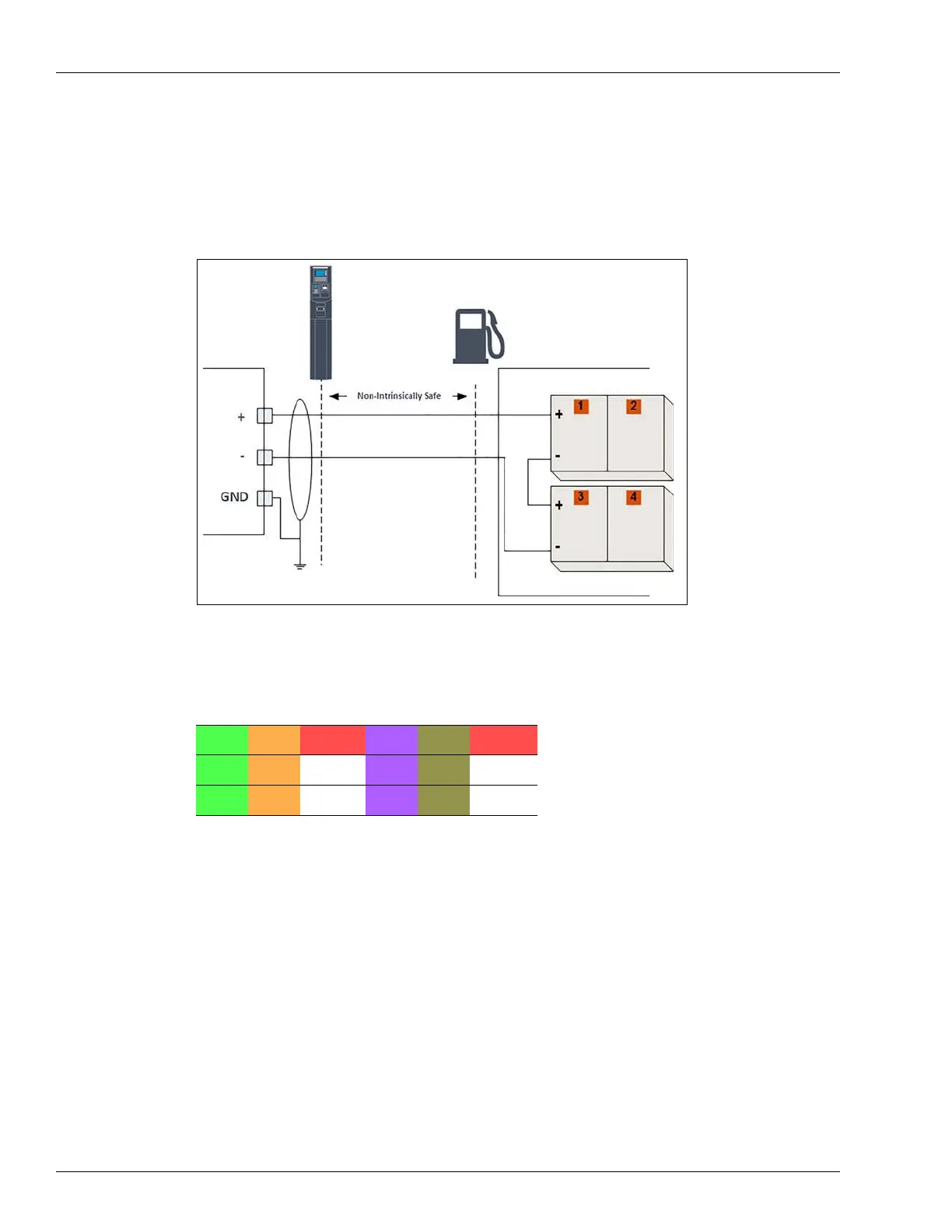
5.5.5.2 Current Loop
The following shows the specific wiring connections between Islander Prime and the Current
Loop pump nozzle, the terminals that differ from the mechanical pump, and the serial
connection between two Current Loop pumps and the terminal block (see Figure 53):
Figure 53: Current Loop Electronic Pump - Wiring Diagram
The Current Loop electronic communication interface is wired according to the following
pinout scheme (see Table 15):
Table 15:
GND1 GND2 CHSS GND3 GND4 CHSS
CLI_1 CLI_2 n.c. CLI_3 CLI_4 n.c.
CLO_1 CLO_2 n.c. CLO_3 CLO_4 n.c.
Current Loop Pinouts
 Loading...