MDE-5411A ForeHB Islander Prime Installation Manual · October 2018 Page 67
5.6 Post-Installation Checklist Installation
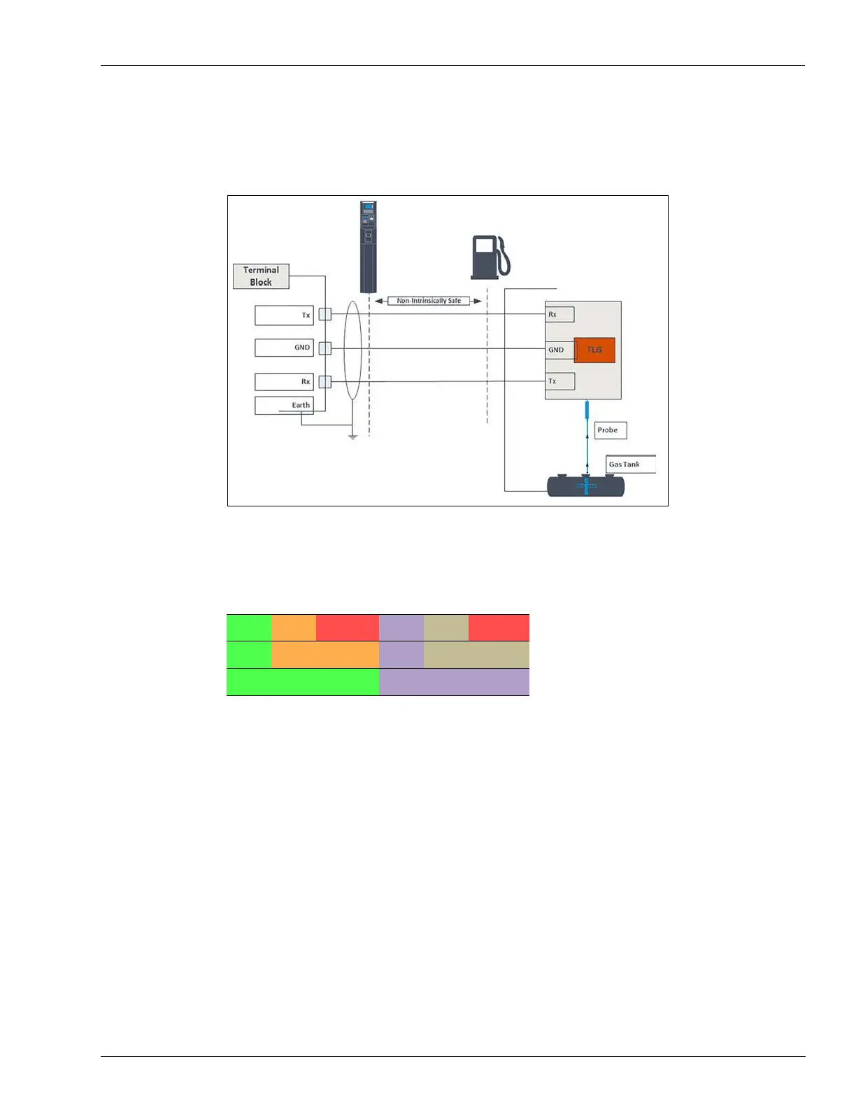
The following shows the required connection between the TLG controller at the site and the
Islander Prime terminal block (see Figure 57):
Figure 57: TLG Wiring Link
The TLG controller communicates via RS-232/422 channels. The RS-232/422 electronic
communication interface is wired according to the following pinout scheme (see Table 17):
Table 17: RS-232/422 Pinouts
5.6 Post-Installation Checklist
After completing the installation procedure, carefully inspect the connection between Islander
Prime and the external power mains and the data sources.
In particular, pay attention to the following:
• Correct wiring
- Is all of the wiring inserted within metal conduits?
- Is the AC and the DC wiring inserted in separate conduits, troughs, etc.?
- Is the system / peripheral equipment powered on a separate dedicated 20 Amp breaker?
- Is the system grounded properly?
- Are the cables correctly routed in the island?
- Are the communication lines under the maximum allowable distance?
o RS-232: 50 feet (15 m)
o RS-485: 330 feet (100 m)
RX_1 RX_ CHSS RX_3 RX_ CHSS
TX_1- TX_ GND2 TX_3- TX_ GND4
TX_1 GND RX_1- TX_3 GND RX_3+