Installation 5.5 Installing Communication Interfaces
Page 62 MDE-5411A ForeHB Islander Prime Installation Manual · October 2018
5.5.5 Electronic Dispenser Connections
The wiring in the terminal block differs in accordance with the type of electronic pump
installed in the homebase station. There are several types of electronic pumps. Electronic
dispenser interfaces may be installed in any of the three slots in the Islander Prime. The
following describes the wiring connections of the available pumps.
Each interface wiring description includes a pinout scheme. The pinout schemes are laid out as
follows:
• The pin number for each cell corresponds with the pin numbers displayed in the Terminal
Blo
ck Map found on the inner wall of the Islander Prime unit.
• Each block of cells shows the channels for each interface type, as follows:
- (Green): Channel #1
- (Peach): Channel #2
-
(Purple): Channel #3
- (Beige): Channel #4
• Each cell defines the signal that is sent over t
hat pin in the terminal block port.
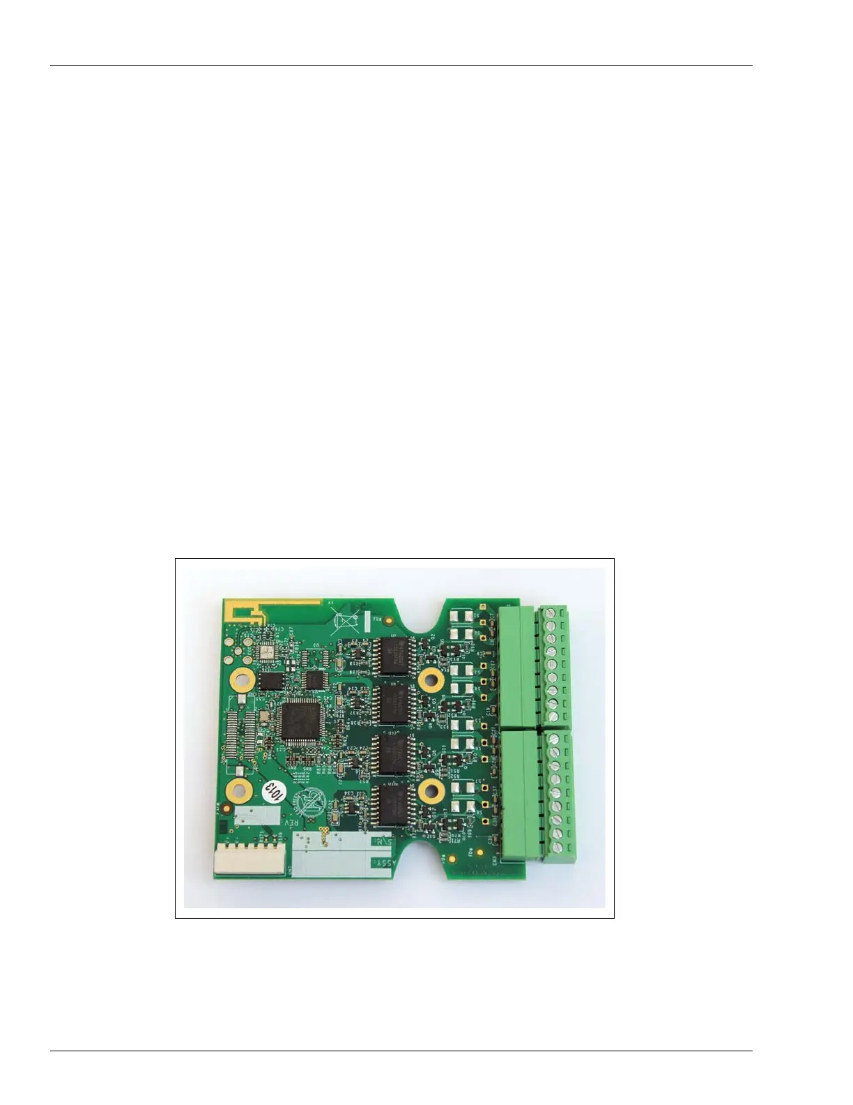
5.5.5.1 Tokheim
The Tokheim electronic interface appears as follows (see Figure 51):
Figure 51: Tokheim Electronic Interface