MDE-5411A ForeHB Islander Prime Installation Manual · October 2018 Page 63
5.5 Installing Communication Interfaces Installation
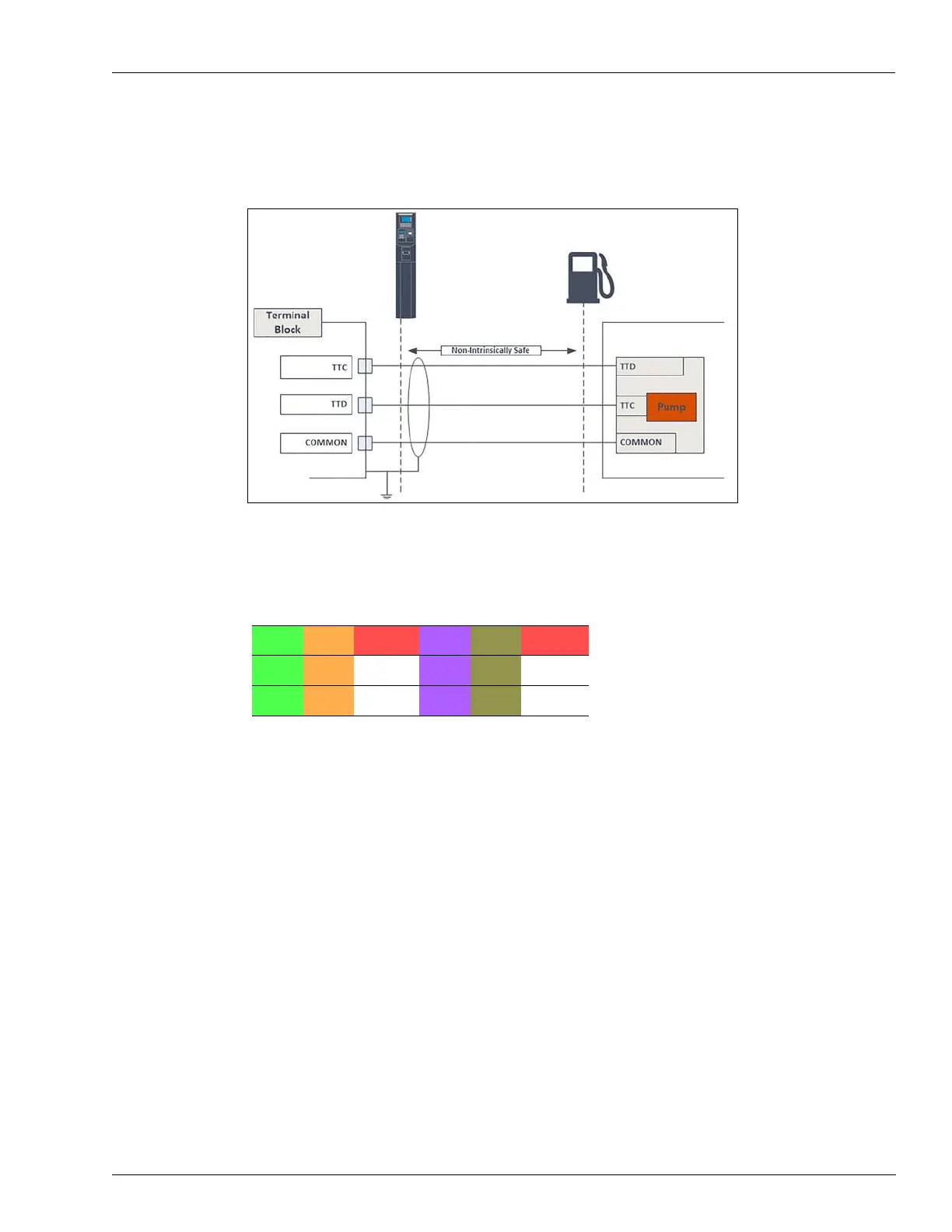
The following shows the specific wiring connections between Islander Prime and the Tokheim
pump nozzle, and the terminals that differ from the mechanical pump (see Figure 52):
Figure 52: Tokheim Electronic Interface - Wiring Diagram
The Tokheim electronic communication interface is wired according to the following pinout
scheme (see Table 14):
Table 14: Tokheim Pinouts
GND1 GND2 CHSS GND3 GND4 CHSS
TTD_1 TTD_2 n.c. TTD_3 TTD_4 n.c.
TTC_1 TTC_2 n.c. TTC_3 TTC_4 n.c.