EasyManuals Logo

GE Dash 4000 Service Manual

GE Dash 4000
282 pages
To Next Page IconTo Next Page
To Previous Page IconTo Previous Page
Page #174 background imageLoading...
Page #174 background image
Field replaceable units: Replace display assembly parts
7-28 Dash 3000/4000/5000 2000966-542D
Replace Dash 4000/5000 alarm light
1. If required, remove the handle assembly. Refer to page 7-10.
2. Remove the display assembly from the main unit. Refer to page 7-18.
3. Open the display assembly. Refer to page 7-27.
4. If required, remove the clear alarm light lens.
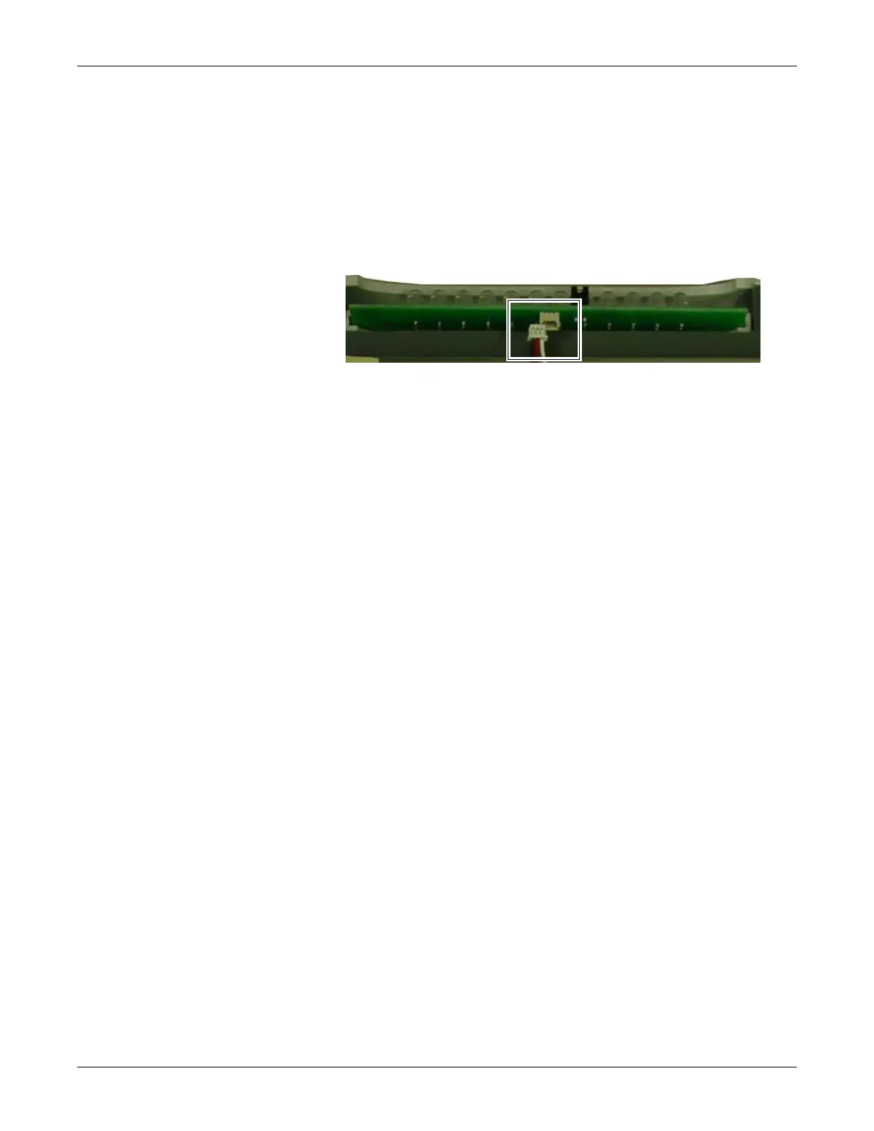
5. Disconnect the alarm light cable from the alarm light PCB.
6. Carefully remove the defective alarm light PCB and set aside.
7. Insert the new alarm light PCB and connect the alarm light cable to
the alarm light PCB connector.
8. Verify the alarm light jumper is secured to both jumper pins. Refer to
step 12 on page 7-22.
9. Re-assemble the patient monitor in reverse order.
10. Complete the procedures in “Recommended checkout” on page 7-52.
Replace display inverter
Follow the steps below for the patient monitor you are servicing.
888A

Table of Contents

Other manuals for GE Dash 4000

Questions and Answers:

Question and Answer IconNeed help?

Do you have a question about the GE Dash 4000 and is the answer not in the manual?

GE Dash 4000 Specifications

General IconGeneral
Resolution640 x 480 pixels
Power Supply100-240 VAC, 50/60 Hz
ECG3/5/12-lead
IBPUp to 4 channels
Battery BackupYes
CertificationsCE, UL, CSA
Parameters MonitoredECG, SpO2, NIBP, IBP, Temperature, Respiration, Cardiac Output
ConnectivityEthernet, USB, Serial
Display TypeTFT LCD
RecorderIntegrated thermal printer
Battery TypeLithium-ion
Operating Temperature0 to 40°C
Storage Temperature-20 to 60°C
Humidity Range15% to 95% non-condensing
Display Size10.4 inches
Cardiac OutputAvailable

Related product manuals