EasyManuals Logo

GE Dash 4000 Service Manual

GE Dash 4000
282 pages
To Next Page IconTo Next Page
To Previous Page IconTo Previous Page
Page #194 background imageLoading...
Page #194 background image
Field replaceable units: Replace main unit parts
7-48 Dash 3000/4000/5000 2000966-542D
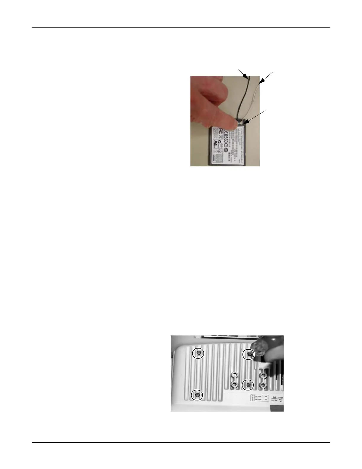
a. Connect the antenna cables to the wireless card (black cable to
the left and grey cable to the right).
b. With the antenna connection facing down, install the card into
the card bracket.
13. Reassemble the patient monitor in reverse order.
14. Be sure to complete the following procedures in “Recommended
checkout” on page 7-52:
electrical safety tests
checkout procedures
calibration
15. Also configure the patient monitor and enable the software options
previously installed. Refer to “Configuration” on page 4-1.
Replace power supply assembly
1. Remove the CPU/battery housing assembly according to steps
starting on page 7-44.
2. While holding the power supply assembly with one hand, remove the
four screws from the back of the unit.
Black antenna cable (left)
Grey antenna cable
(right)
Antenna connectors
959C
575A

Table of Contents

Other manuals for GE Dash 4000

Questions and Answers:

Question and Answer IconNeed help?

Do you have a question about the GE Dash 4000 and is the answer not in the manual?

GE Dash 4000 Specifications

General IconGeneral
Resolution640 x 480 pixels
Power Supply100-240 VAC, 50/60 Hz
ECG3/5/12-lead
IBPUp to 4 channels
Battery BackupYes
CertificationsCE, UL, CSA
Parameters MonitoredECG, SpO2, NIBP, IBP, Temperature, Respiration, Cardiac Output
ConnectivityEthernet, USB, Serial
Display TypeTFT LCD
RecorderIntegrated thermal printer
Battery TypeLithium-ion
Operating Temperature0 to 40°C
Storage Temperature-20 to 60°C
Humidity Range15% to 95% non-condensing
Display Size10.4 inches
Cardiac OutputAvailable

Related product manuals