Home
GE
Relays
L90
Page 388
GE L90 - Page 388
900 pages
Manual
Save Page as PDF
To Next Page
To Next Page
To Previous Page
To Previous Page
Loading...
5-164
L90 LINE CURRENT D
IFFERENT
IAL SY
STEM – INSTRUCTION MANUAL
SYSTEM SETUP
CHAPTER 5: SETTINGS
5
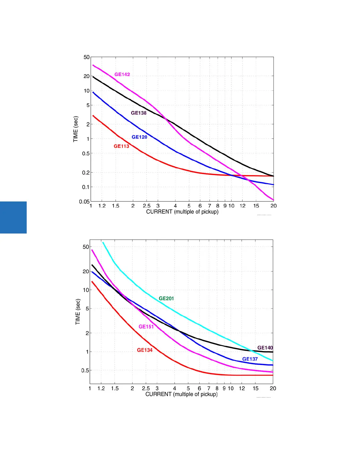
Figure 5-77: R
ecloser curves GE113, GE120, GE138, and GE142
Figure 5-78: R
ecloser curves GE
134, GE137, GE140, GE151, and GE201
387
389
Table of Contents
Main Page
Default Chapter
3
Table of Contents
3
1 Introduction
11
Safety Symbols and Definitions
11
General Cautions and Warnings
11
For Further Assistance
12
2 Product Description
15
Description
16
Features
17
Pilot Channel Relaying
19
Inter-Relay Communications
19
Channel Monitor
21
Loopback Test
21
Direct Transfer Tripping
22
Security
22
Order Codes
25
Order Codes with Enhanced CT/VT Modules
26
Order Codes with Process Bus Modules
33
Replacement Modules
40
Signal Processing
42
UR Signal Processing
42
Specifications
44
Protection Elements
45
User-Programmable Elements
54
Monitoring
56
Metering
57
Inputs
58
Power Supply
59
Outputs
60
Communication Protocols
62
Inter-Relay Communications
63
Cybersentry Security
64
Graphical Front Panel
64
Environmental
65
Type Tests
66
Production Tests
66
Approvals
67
Maintenance
67
3 Installation
69
Unpack and Inspect
69
Panel Cutouts
70
Horizontal Units
70
Vertical Units
73
Rear Terminal Layout
78
Wiring
80
Typical Wiring
80
Dielectric Strength
81
Control Power
81
CT/VT Modules
82
Process Bus Modules
84
Contact Inputs and Outputs
84
Transducer Inputs and Outputs
95
RS232 Port
97
CPU Communication Ports
98
Irig-B
100
Pilot Channel Communications
101
Fiber: LED and ELED Transmitters
102
Fiber Laser Transmitters
102
Interface
103
RS422 Interface
107
Two-Channel Two-Clock RS422 Interface
109
RS422 and Fiber Interface
110
And Fiber Interface
110
IEEE C37.94 Interface
111
C37.94SM Interface
114
Activate Relay
117
Install Software
118
Enervista Communication Overview
118
System Requirements
119
Add Device to Software
120
Set IP Address in UR
121
Configure Serial Connection
126
Configure Ethernet Connection
127
Configure Modem Connection
129
Automatic Discovery of UR Devices
129
Connect to the L90
130
Connect to the L90 in Enervista
130
Use Quick Connect Via the Front Panel RS232 Port
131
Use Quick Connect Via a Rear Ethernet Port
132
Set up Cybersentry and Change Default Password
133
Import Settings
133
Connect to D400 Gateway
134
Oscillography Files
134
Event Records
134
Log Files
134
Setting Files
135
4 Interfaces
137
Enervista Software Interface
137
Introduction
137
Settings Files
137
Event Viewing
138
File Support
139
Enervista Main Window
139
Protection Summary Window
140
Settings Templates
141
Secure and Lock Flexlogic Equations
145
Settings File Traceability
148
Front Panel Interface
150
Front Panel
150
Front Panel Display
153
Front Panel Navigation Keys
174
LED Indicators
176
Front Panel Labelling
180
Menu Navigation
187
Change Settings
189
View Actual Values
194
Breaker Control
195
Change Passwords
196
Logic Diagrams
198
Invalid Password Entry
198
Flexlogic Design Using Engineer
199
Design Logic
201
Send File to and from Device
211
Monitor Logic
212
View Front Panel and Print Labels
213
Generate Connectivity Report
214
Preferences
214
Toolbars
218
5 Settings
225
Overview
228
Introduction to Elements
228
Introduction to AC Sources
230
Product Setup
232
Security
232
Display Properties
251
Graphical Front Panel
253
Clear Relay Records
265
Communications
266
Modbus User Map
332
Real-Time Clock
332
Fault Reports
337
Oscillography
340
Data Logger
342
Demand
343
User-Programmable Leds
345
User-Programmable Self-Tests
349
Control Pushbuttons
350
User-Programmable Pushbuttons
351
Flex State Parameters
357
User-Definable Displays
358
Installation
359
Remote Resources
360
Remote Resources Configuration
360
System Setup
361
AC Inputs
361
Power System
362
Signal Sources
363
Power System
366
Breakers
374
Disconnect Switch Control
379
Flexcurves
384
Phasor Measurement Unit
391
Flexlogic
411
Flexlogic Operands
411
Flexlogic Rules
427
Flexlogic Evaluation
428
Flexlogic Example
428
Flexlogic Equation Editor
433
Flexlogic Timers
433
Flexelements
433
Non-Volatile Latches
438
Grouped Elements
440
Overview
440
Setting Group 1
440
Line Differential Elements
440
Line Pickup
446
Distance
448
Power Swing Detect (ANSI 68)
469
Load Encroachment
478
Phase Current
479
Neutral Current
491
Wattmetric Ground Fault
499
Ground Current
503
Negative Sequence Current
510
Breaker Failure (ANSI 50BF)
516
Voltage Elements
526
Supervising Elements
538
Sensitive Directional Power
545
Control Elements
548
Overview
548
Trip Bus
549
Setting Groups
550
Selector Switch
552
Trip Output
558
Underfrequency (ANSI 81U)
564
Overfrequency (ANSI 81O)
565
Synchrocheck (ANSI 25)
566
Digital Elements
571
Digital Counters
574
Monitoring Elements
576
Pilot Schemes
600
Autoreclose (ANSI 79)
623
Frequency Rate of Change (ANSI 81R)
636
Inputs/Outputs
637
Contact Inputs
637
Virtual Inputs
639
Contact Outputs
640
Virtual Outputs
644
Direct Inputs and Outputs
644
Resetting
645
Transducer Inputs/Outputs
646
Dcma Inputs
646
RTD Inputs
647
Dcma Outputs
649
Testing
652
Test Mode Function
652
Test Mode Forcing
653
Phasor Measurement Unit Test Values
653
Force Contact Inputs
655
Force Contact Outputs
655
Channel Tests
656
6 Actual Values
657
Actual Values Menu
657
Front Panel
659
Status
660
Contact Inputs
660
Virtual Inputs
660
Rxgoose Boolean Inputs
661
Rxgoose DPS Inputs
661
Direct Inputs
661
Contact Outputs
661
Virtual Outputs
662
Rxgoose Status
662
Rxgoose Statistics
662
Autoreclose
663
Channel Tests
663
Digital Counters
664
Selector Switches
665
Flex States
665
Ethernet
665
Real Time Clock Synchronizing
665
Remaining Connection Status
666
Parallel Redundancy Protocol (PRP)
667
Txgoose Status
667
Metering
668
Metering Conventions
668
Differential Current
672
Sources
673
Sensitive Directional Power
679
Synchrocheck
679
Tracking Frequency
680
Frequency Rate of Change
680
Flexelements
680
Rxgoose Analogs
681
Wattmetric Ground Fault
681
Phasor Measurement Unit
681
PMU Aggregator
682
Volts Per Hertz
682
Restricted Ground Fault
683
Transducer Inputs and Outputs
683
Distance
683
Records
685
Fault Reports
685
Event Records
686
Oscillography
688
Data Logger
688
Phasor Measurement Unit Records
689
Breaker Maintenance
689
Product Information
690
Model Information
690
Firmware Revisions
690
7 Commands and Targets
693
Commands Menu
693
Virtual Inputs
694
Clear Records
694
Set Date and Time
695
Relay Maintenance
695
Phasor Measurement Unit One-Shot
696
Security
698
Targets Menu
698
Target Messages
699
Relay Self-Tests
699
8 Application of Settings
709
CT Requirements
709
Introduction
709
CT Saturation Analysis Tool
710
Current Differential (87L) Settings
711
Introduction
711
Current Differential Pickup
712
Current Differential Restraint 1
712
Current Differential Break Point
712
CT Tap
712
Breaker-And-A-Half
714
Distributed Bus Protection
717
Channel Asymmetry Compensation Using GPS
718
Introduction
718
Compensation Method 1
718
Compensation Method 2
719
Compensation Method 3
720
Distance Backup/Supervision
721
Overview
721
Phase Distance
722
Ground Distance
723
Protection Signaling Schemes
724
Overview
724
Direct Under-Reaching Transfer Trip (DUTT)
725
Permissive Under-Reaching Transfer Trip (PUTT)
725
Permissive Over-Reaching Transfer Trip (POTT)
725
Hybrid POTT Scheme (HYB-POTT)
726
Directional Comparison Blocking
727
Directional Comparison Unblocking
727
Series Compensated Lines
729
Distance Settings
729
Ground Directional Overcurrent
731
Lines with Tapped Transformers
731
Overview
731
Transformer Load Currents
732
LV-Side Faults
732
External Ground Faults
732
Instantaneous Elements
733
Instantaneous Element Error During L90 Synchronization
733
Phase Distance through Power Transformers
734
Phase Distance Protection
734
Example
735
9 Commissioning
737
Testing
737
Channel Testing
737
Clock Synchronization Tests
738
Current Differential
739
Local-Remote Relay Tests
740
10 Theory of Operation
743
L90 Design
743
L90 Architecture
744
Removal of Decaying Offset
744
Phaselet Computation
744
Disturbance Detection
745
Fault Detection
745
Ground Differential Element
747
Clock Synchronization
748
Frequency Tracking and Phase Locking
748
Frequency Detection
749
Phase Detection
750
Phase Locking Filter
752
Matching Phaselets
753
Start-Up
754
Hardware and Communication Requirements
754
Online Estimate of Measurement Errors
754
CT Saturation Detection
755
Charging Current Compensation
756
Differential Element Characteristics
757
Relay Synchronization
758
Operating Condition Characteristics
759
Description
759
Trip Decision Example
761
Trip Decision Test
761
Distance Elements
762
Introduction
762
Phasor Estimation
763
Distance Characteristics
763
Fast Distance Algorithm
768
Memory Polarization
769
Distance Elements Analysis
770
Phase Distance Applied to Power Transformers
773
Description
773
Example
777
Overview
779
Single-Pole Tripping
779
Phase Selection
782
Communications Channels for Pilot-Aided Schemes
784
Permissive Echo Signaling
790
Pilot Scheme / Phase Selector Coordination
791
Cross-Country Fault Example
792
Fault Locator
793
Overview
793
Multi-Ended Fault Locator
793
Single-Ended Fault Locator
800
11 Maintenance
805
Devices with Site Targets
805
Data with Modbus Analyzer
805
Monitoring
805
General Maintenance
807
In-Service Maintenance
807
Out-Of-Service Maintenance
807
Unscheduled Maintenance (System Interruption)
807
Retrieve Files
807
Cybersentry Security Event Files
808
Convert Device Settings
809
Copy Settings to Other Device
811
Compare Settings
811
Compare against Defaults
811
Compare Two Devices
812
Back up and Restore Settings
812
Back up Settings
812
Restore Settings
815
Upgrade Software
817
Upgrade Firmware
817
Replace Front Panel
819
Replace Module
827
Battery
828
Replace Battery for SH/SL Power Supply
828
Dispose of Battery
830
Clear Files and Data after Uninstall
833
Repairs
833
Storage
834
Disposal
834
Flexanalog Items
835
A.1 Flexanalog Items
835
B Radius Server
865
RADIUS Server Configuration
865
C Command Line
867
Command Line Interface
867
Warranty
873
Revision History
873
D.1 Warranty
873
Related product manuals
GE UR Series L90
846 pages
GE L30
698 pages
GE LPS-O
308 pages
GE IAC
32 pages
GE 489
306 pages
GE 469
336 pages
GE C60
682 pages
GE 345
82 pages
GE 750
504 pages
GE B90
510 pages
GE UR series
652 pages
GE Multilin 489
314 pages