CHAPTER 10: THEORY OF OPERATION FAULT LOCATOR
L90 LINE CURRENT DIFFERENTIAL SYSTEM – INSTRUCTION MANUAL 10-55
10
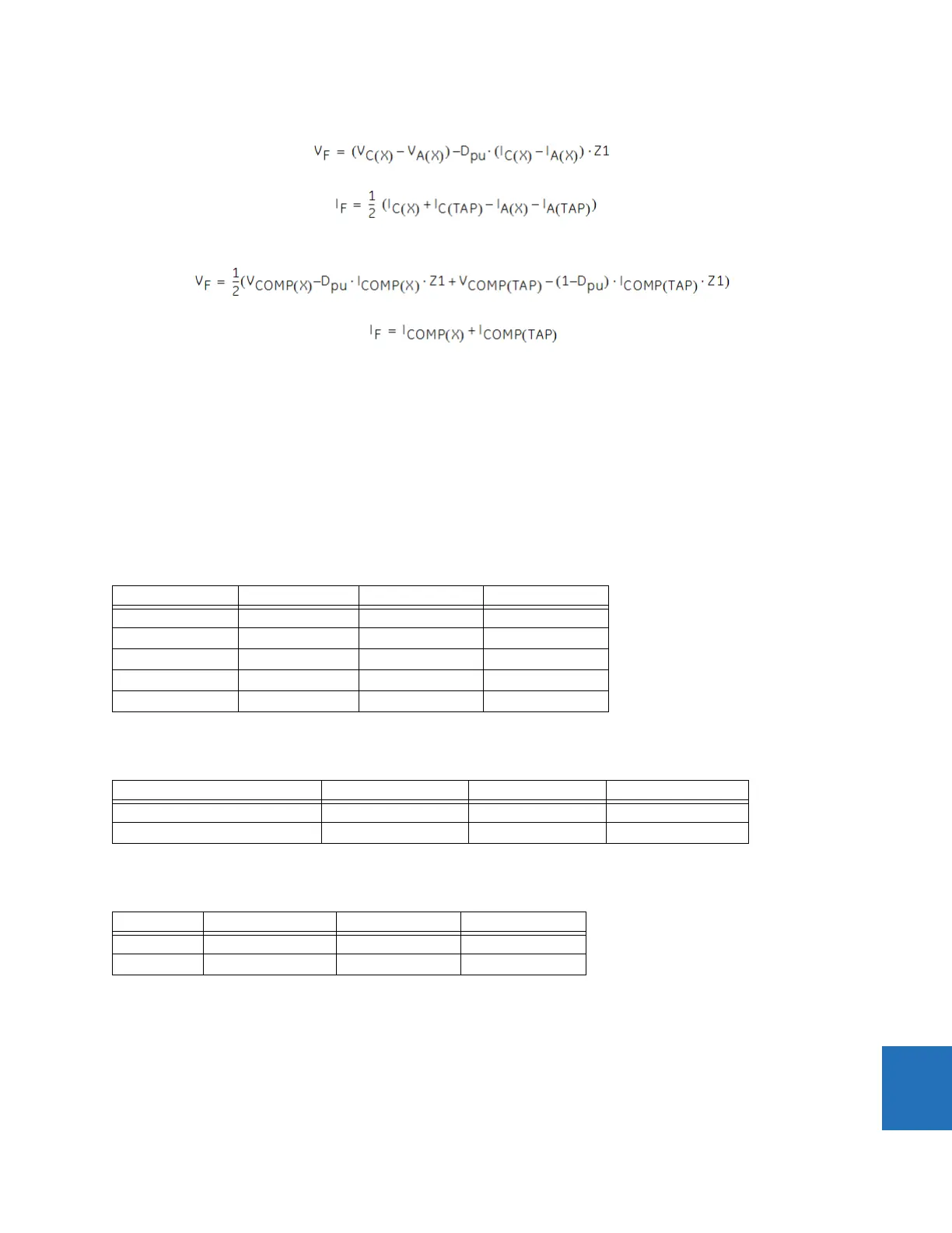
For CA/CAG faults:
Eq. 10-69
Eq. 10-70
For ABC faults:
Eq. 10-71
Eq. 10-72
where
V
COMP
and I
COMP
are the composite voltage and composite current
I0M = IG/3 and IG is the ground current of the adjacent parallel line
The two terminal equations are similar, and only need replace the subscript of (X) and (TAP) with (LOC) and (REM).
10.6.2.3 Example
Consider a three-terminal, 500 kV application with no charging current compensation or zero-sequence removal. The
phase rotation is ABC and the following CT and VT data is known.
Table 10-37: CT and VT application data for multi-ended example (assumes 87L and fault locator sources are identi-
cal)
The following table shows the tap settings.
Table 10-38: Tap settings for multi-ended example
The following table shows the primary positive-sequence impedances and length for the line.
Table 10-39: Line length and positive sequence impedance for multi-ended example
The figure shows how the three relays are connected.
Value Relay 1 Relay 2 Relay 3
CT primary 1200 A 1000 A 1600 A
CT secondary 5 A 1 A 5 A
VT connection wye delta wye
VT secondary 57.73 V 83.33 V 57.73 V
VT ratio 5000:1 6000:1 5000:1
Value Relay 1 Relay 2 Relay 3
CT tap 1 for remote terminal 1 1000 / 1200 = 0.8333 1200 / 1000 = 1.200 1200 / 1600 = 0.750
CT tap 1 for remote terminal 2 1600 / 1200 = 1.3333 1600 / 1000 = 1.600 1000 / 1600 = 0.625
Value Relay 1 to tap Relay 2 to tap Relay 3 to tap
Impedance 21.29 Ω ∠80.5° 36.50 Ω ∠80.5° 16.73 Ω ∠80.5°
Length 70 km 120 km 55 km