10-56 L90 LINE CURRENT DIFFERENTIAL SYSTEM – INSTRUCTION MANUAL
FAULT LOCATOR CHAPTER 10: THEORY OF OPERATION
10
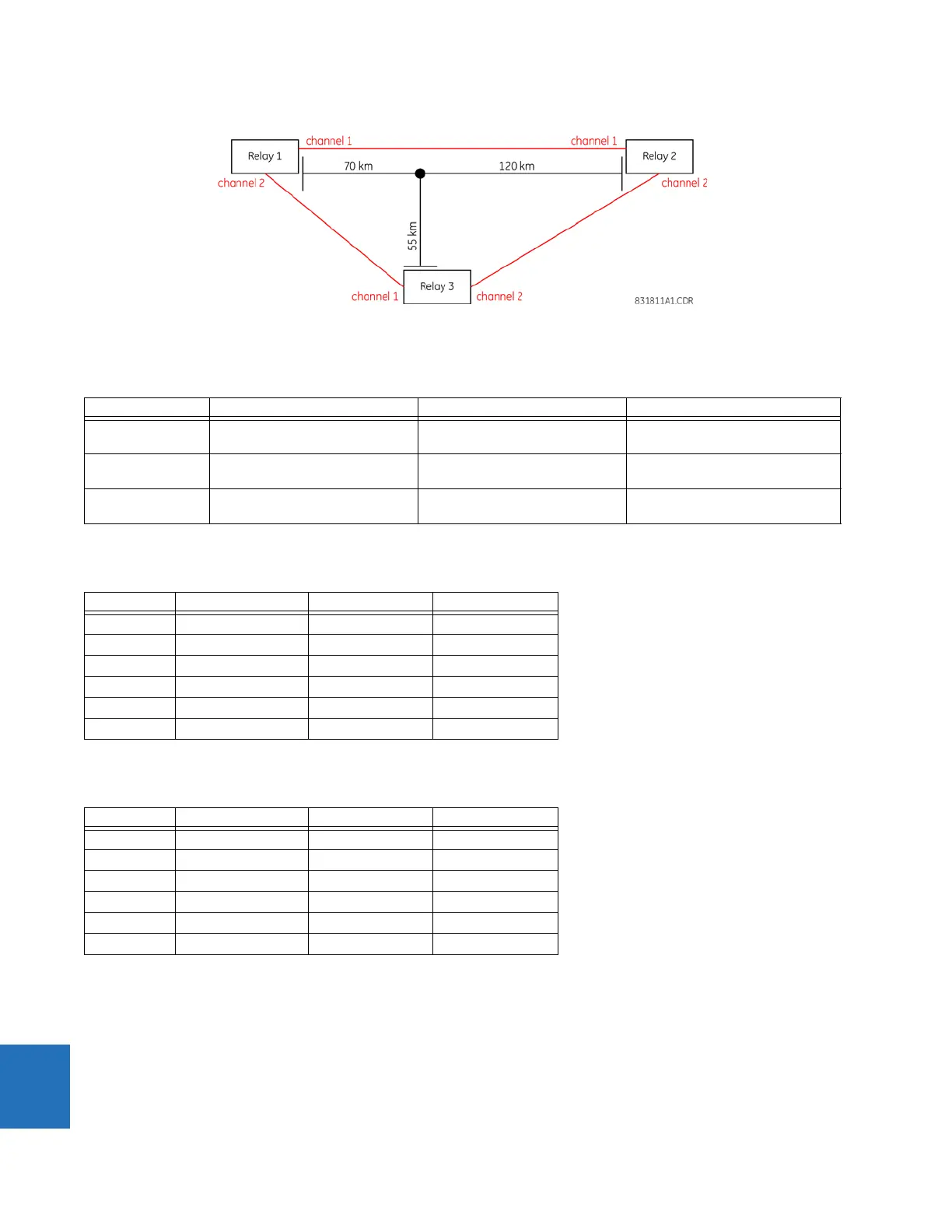
Figure 10-17: Relay connections for multi-ended fault locator example
The following settings are entered into the relays by you. These values are calculated in secondary ohms as shown in the
following tables.
Table 10-40: Line impedance settings (all angles are 80.5°)
Assume that the following signals are measured by the relays when the fault locator is triggered.
Table 10-41: Relay measurements (physical inputs)
These measurements are shown as follows in per-unit values of the CT and VT nominal of the 87L source.
Table 10-42: Relay measurements (per-unit values)
When subjected to the expanded Clarke transform in the previous section, the local currents yield the following values (in
relay per-unit values):
• Relay 1: 1.3839 pu ∠–84.504°
• Relay 2: 5.4844 pu ∠–85.236°
• Relay 3: 1.2775 pu ∠–56.917°
When subjected to the expanded Clarke transform in the previous section, the local voltages yield the following values (in
per-unit values of the nominal primary phase-to-ground voltage):
Value Relay 1 Relay 2 Relay 3
Local to tap 1.0219 sec. ohms (relay 1 to tap in
relay 1 secondary ohms)
6.0833 sec. ohms (relay 2 to tap in
relay 2 secondary ohms)
1.0707 sec. ohms (relay 3 to tap in
relay 3 secondary ohms)
Remote 1 to tap 1.7520 sec. ohms (relay 2 to tap in
relay 1 secondary ohms)
3.5483 sec. ohms (relay 1 to tap in
relay 2 secondary ohms)
1.3626 sec. ohms (relay 1 to tap in
relay 3 secondary ohms)
Remote 2 to tap 0.8030 sec. ohms (relay 3 to tap in
relay 1 secondary ohms)
2.7883 sec. ohms (relay 3 to tap in
relay 2 secondary ohms)
2.3360 sec. ohms (relay 2 to tap in
relay 3 secondary ohms)
Value Relay 1 Relay 2 Relay 3
F1 10.64 A ∠–87.5° 8.592 A ∠–88.5° 9.652 A ∠–43°
F2 1.652 A ∠88.9° 1.273 A ∠78.6° 5.201 A ∠–99°
F3 1.66 A ∠–31.2° 1.614 A ∠–43° 6.269 A ∠139.3°
F5 52.71 V ∠0.8° 76.943 V ∠24.579° 49.6 V ∠10.1°
F6 58.21 V ∠–121.4° 86.321 V ∠–98.052° 57.1 V ∠–115.6°
F7 58.93 V ∠121.9° 78.795 V ∠137.27° 59.12 V ∠130.8°
Value Relay 1 Relay 2 Relay 3
IA 2.128 pu ∠–87.5° 8.592 pu ∠–88.5° 1.9304 pu ∠–43°
IB 0.3304 pu ∠88.9° 1.273 pu ∠78.6° 1.0402 pu ∠–99°
IC 0.332 pu ∠–31.2° 1.614 pu ∠–43° 1.2538 pu ∠139.3°
VA (VAB) 0.91304 pu ∠0.8° 0.92335 pu ∠24.579° 0.85917 pu ∠10.1°
VB (VBC) 1.0083 pu ∠–121.4° 1.0359 pu ∠–98.052° 0.98909 pu ∠–115.6°
VC (VCA) 1.0208 pu ∠121.9° 0.94557 pu
∠137.27° 1.0241 pu ∠130.8°

 Loading...


