CHAPTER 10: THEORY OF OPERATION FAULT LOCATOR
L90 LINE CURRENT DIFFERENTIAL SYSTEM – INSTRUCTION MANUAL 10-57
10
• Relay 1: 0.38781 pu ∠0.26811°
• Relay 2: 0.30072 pu ∠–12.468°
• Relay 3: 0.37827 pu ∠8.9388°
Since they have a common per-unit base, the composite voltages are used at all locations. The currents are ratio matched
using the tap settings.
For example, the composite current at relay 1 is 1.3839 pu of its local CT; that is, 1.3839 × 1200 A = 1.6607 kA. When
calculated at relay 2 from the data sent from relay 1 to relay 2, this value is 1.6607 kA / 1000 A = 1.6607 pu of the relay 2 CT.
This is due to the procedure of applying tap settings to the received phase currents before calculating the composite
signal.
As a result, the three relays work with the following signals.
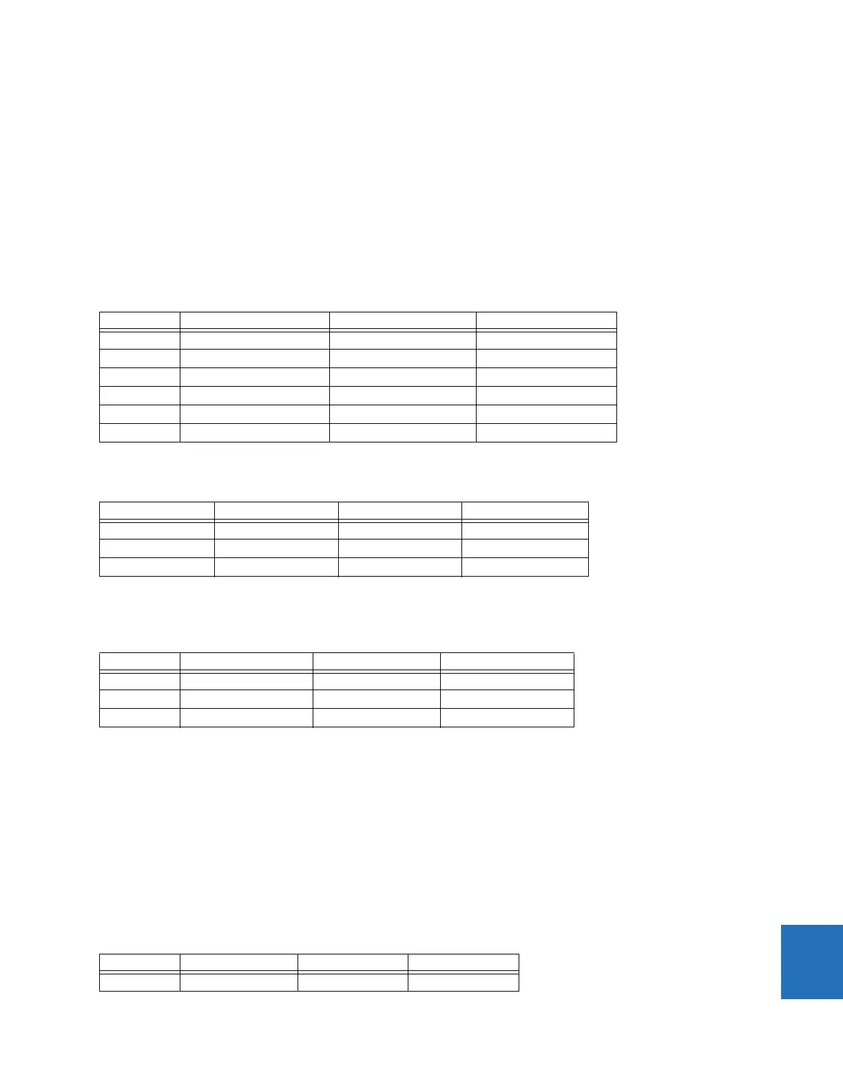
Table 10-43: Composite signals at all three relays
The line impedances entered in secondary ohms are recalculated as follows (refer to the previous section for equations).
Table 10-44: Per-unit line impedance
Using the data in the previous two tables, the tap voltages are calculated as follows (refer to the previous section for
equations).
Table 10-45: Calculated tap voltages using terminal data
From this table, it is visible that
• Looking from relay 1, there is no fault between the tap and the local terminal and between the tap and remote 2
terminal. Therefore, the fault must be between the remote 1 terminal = relay 2 and the tap.
• Looking from relay 2, there is no fault between the tap and the remote 1 terminal, and between the tap and remote 2
terminal. Therefore, the fault must be between the local terminal = relay 2 and the tap.
• Looking from relay 3, there is no fault between the tap and the remote 1 terminal, and between the tap and the local
terminal. Therefore, the fault must be between the remote 2 terminal = relay 2 and the tap.
Note that the correct value of the tap voltage is equal for all three relays. This is expected since the per-unit base for the
composite voltages is equal for all three relays.
The three relays calculate the differences as follows (refer to the previous section for equations).
Table 10-46: Tab voltage differences using terminal data
Value Relay 1 Relay 2 Relay 3
V
LOC(X)
0.38781 pu ∠0.26811° 0.30072 pu ∠–12.468° 0.37827 pu ∠8.9388°
V
REM1(X)
0.30072 pu ∠–12.468° 0.38781 pu ∠0.26811° 0.38781 pu ∠0.26811°
V
REM2(X)
0.37827 pu ∠8.9388° 0.37827 pu ∠8.9388° 0.30072 pu ∠–12.468°
I
LOC(X)
1.3839 pu ∠–84.504° 5.4844 pu ∠–85.236° 1.2775 pu ∠–56.917°
I
REM1(X)
4.5704 pu ∠–85.236° 1.6607 pu ∠–84.504° 1.0379 pu ∠–84.504°
I
REM2(X)
1.7033 pu ∠–56.917° 2.0439 pu ∠–56.917° 3.4278 pu ∠–85.236°
Value Relay 1 Relay 2 Relay 3
Local to tap 0.088509 pu ∠80.5° 0.12644 pu ∠80.5° 0.092735 pu ∠80.5°
Remote 1 to tap 0.15174 pu ∠80.5° 0.073754 pu ∠80.5° 0.11801 pu ∠80.5°
Remote 2 to tap 0.069551 pu ∠80.5° 0.057957 pu ∠80.5° 0.20232 pu ∠80.5°
Value Relay 1 Relay 2 Relay 3
V
T(LOC)
0.26581 pu ∠2.2352° 0.39755 pu ∠–178.9° 0.26535 pu ∠2.4583°
V
T(REM1)
0.39758 pu ∠–178.9° 0.26582 pu ∠2.2351° 0.26581 pu ∠2.2352°
V
T(REM2)
0.26535 pu ∠2.4583° 0.26535 pu ∠2.4587° 0.39758 pu ∠–178.9°
Value Relay 1 Relay 2 Relay 3
LOC-REM1 0.66337 pu 0.66334 pu 0.0011344 pu