CHAPTER 10: THEORY OF OPERATION FAULT LOCATOR
L90 LINE CURRENT DIFFERENTIAL SYSTEM – INSTRUCTION MANUAL 10-61
10
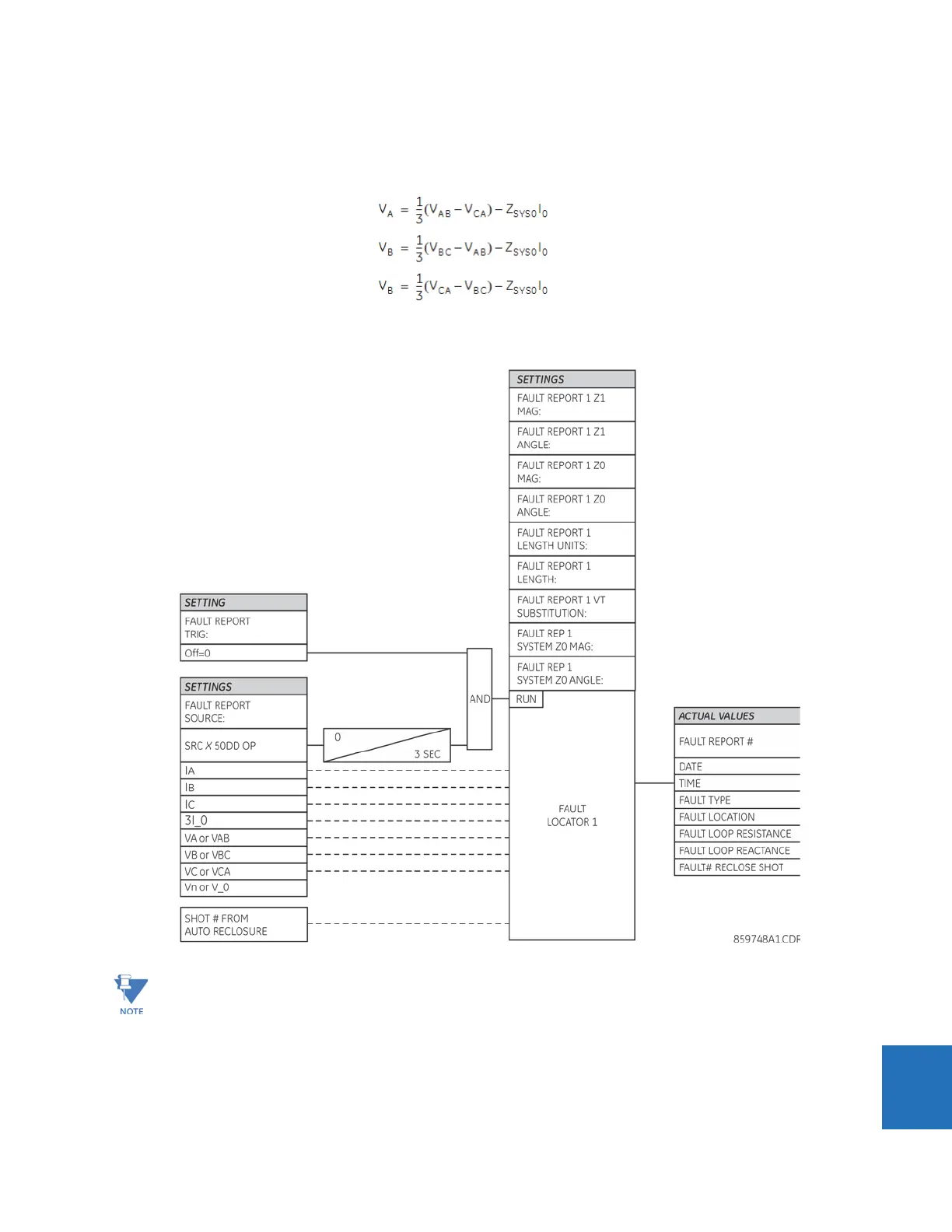
If the FAULT REPORT 1 VT SUBSTITUTION setting value is “I0” and the VTs are connected in a wye configuration, the fault
location is performed based on the actual phase to ground voltages. If the VTs are connected in a delta configuration, fault
location is performed based on the delta voltages and zero-sequence voltage approximated based on the zero-sequence
current:
Eq. 10-84
where Z
SYS0
is the equivalent zero-sequence impedance behind the relay as entered under the fault report setting menu.
Figure 10-20: Fault locator scheme
Since the fault locator algorithm is based on the single-end measurement method, in three-terminal configuration
the estimation of fault location may not be correct at all three terminals especially if fault occurs behind the line's
tap respective to the given relay.