10-60 L90 LINE CURRENT DIFFERENTIAL SYSTEM – INSTRUCTION MANUAL
FAULT LOCATOR CHAPTER 10: THEORY OF OPERATION
10
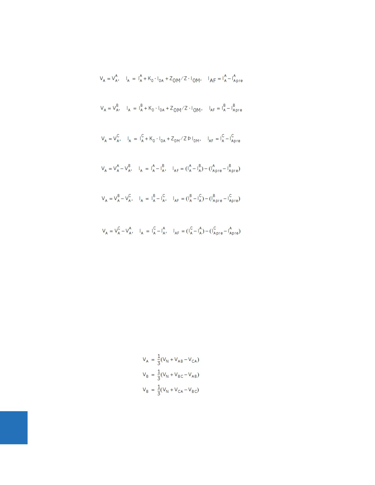
Depending on the fault type, appropriate voltage and current signals are selected from the phase quantities before
applying the preceding equation (the superscripts denote phases, the subscripts denote stations).
For AG faults:
Eq. 10-77
For BG faults:
Eq. 10-78
For CG faults:
Eq. 10-79
For AB and ABG faults:
Eq. 10-80
For BC and BCG faults:
Eq. 10-81
For CA and CAG faults:
Eq. 10-82
where K
0
is the zero sequence compensation factor (for the first six equations)
Z
0M
is the mutual zero sequence impedance
I
0M
= I
G
/3 and I
G
is the ground current of the adjacent line. The I
0M
compensation term is applied for the entirely parallel
line.
For ABC faults, all three AB, BC, and CA loops are analyzed and the final result is selected based upon consistency of the
results.
The element calculates the distance to the fault (with m in miles or kilometers) and the phases involved in the fault.
The relay allows locating faults from delta-connected VTs. If the
FAULT REPORT 1 VT SUBSTITUTION setting is set to “None,”
and the VTs are connected in wye, the fault location is performed based on the actual phase to ground voltages. If the VTs
are connected in delta, fault location is suspended.
If the
FAULT REPORT 1 VT SUBSTITUTION setting value is “V0” and the VTs are connected in a wye configuration, the fault
location is performed based on the actual phase to ground voltages. If the VTs are connected in a delta configuration, fault
location is performed based on the delta voltages and externally supplied neutral voltage:
Eq. 10-83