5-
14
LPS-O Line Protection System GE Power Management
5.3 PHASE-TO-PHASE ZONE REACH TESTING 5 FUNCTIONAL TESTS (FACTORY SETTINGS)
5
5. Set the fault current to 10.0 (2.0) amps rms. Simultaneously reduce the voltages of the faulted phases and
check that the A1 contact closes when the voltages are within the limits shown in Table 5–5: FAULT CUR-
RENT PHASE SETTINGS FOR TEST T14.
6. Reduce the fault current to zero. Note that the trip target indication concurs with the fault. For example, an
AB fault is displayed as follows:
TRIP AB Z4 “DIST”
where “DIST” is the displayed target.
7. Repeat the test for phase BC and CA faults.
5.3.5 T15 – 3 PHASE FAULT WITH TRANSFORMER COMPENSATION
1. Protection Settings:
Z1DISTANCE
(101)
Z1PHASE
= YES
(102)
Z1PREACH
= 6.03
Ω
(104)
Z1P_TIME
= 0.0 sec.
Z2DISTANCE
(201)
Z2PHASE
= NO
Z3DISTANCE
(301)
Z3PHASE
= NO
Z4DISTANCE
(401)
Z4PHASE
= NO
LINEINFO
(1204)
TRSFMRTYPE
= YD1
2. Connect the relay as shown in Figure 5–2: THREE PHASE TEST CONNECTIONS. Set the relay to test
mode 14 (Any Zone 1 Phase). The LUI displays:
ANY Z1 PHASE ON
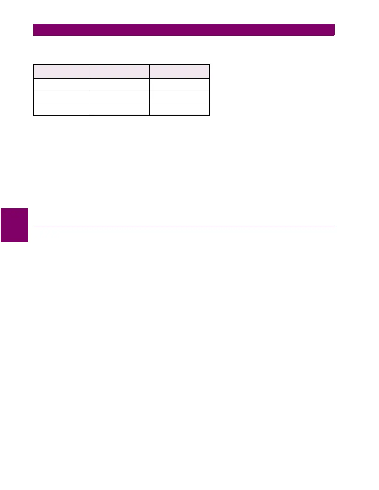
Table 5–5: FAULT CURRENT PHASE SETTINGS FOR TEST T14
I Degrees Volts rms
Displayed Target
†
–25 56 to 63 –
–55 64 to 72 290 to 310
–85 56 to 63 –
†
Reference only