9-
2
LPS-O Line Protection System GE Power Management
9.2 SERVICING WITH THE RELAY SELF-TEST 9 SERVICING
9
9.2 SERVICING WITH THE RELAY SELF-TEST 9.2.1 DESCRIPTION
The LPS-O automatically performs tests of major functions and critical hardware components and reports their
status via the LUI Display, status LED, and the non-critical and critical alarm contacts. The failure report is
dependent on the type or level of failure. Some failures operate the critical alarm contact and the status LED,
while others only operate the non-critical alarm contact.
There are three levels of self-test performed by the LPS-O:
1. The first level indicates severe relaying failures. These are indicated by a FAIL message on the display, the
critical alarm contact opening, and the status LED turning red. These failures indicate that the relay is not
providing protection.
2. The second level displays warning messages. They are indicated by a WARN message on the display and
closure of the non-critical alarm contact. These failures indicate that the relay is still providing some degree
of protection.
3. The third level indicates system status errors that are due to power system errors (Trip Circuit Open) or are
caused by an LPS-O command that disables the relay (Disable Outputs). They are indicated by the closing
of the non-critical alarm contact, a red status LED, or by the opening of the critical alarm contact. However,
nothing is displayed until the Information Status command is issued.
The types of self-tests performed are described in Section 1.7: SELF-TEST FEATURES on page 1–18. The
components tested during the start-up self-tests are listed in Table 9–1 below. The components tested during
run-time background and foreground self-tests are listed in Tables 9–2 and 9–3 respectively
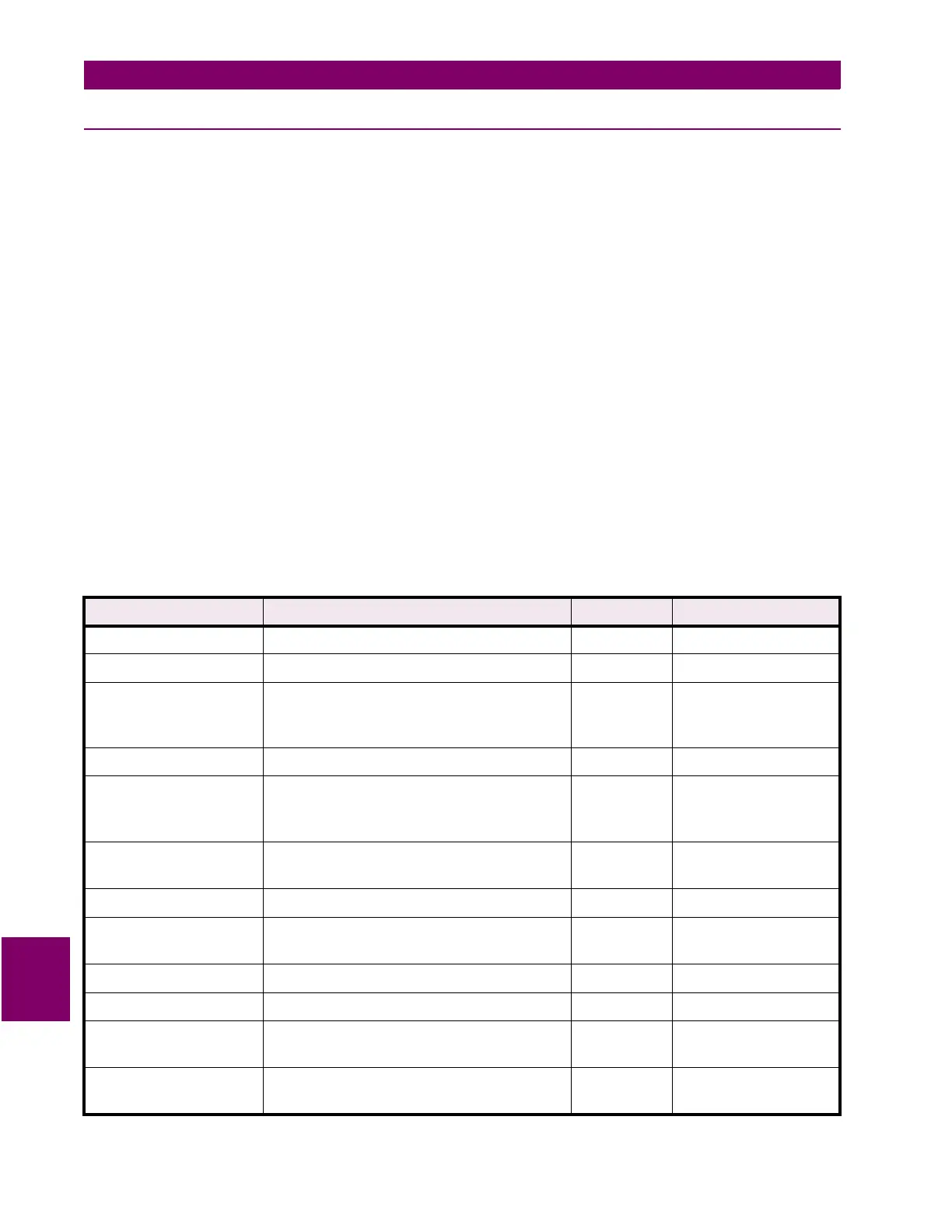
Table 9–1: COMPONENTS TESTED DURING START-UP TESTS
Component Method Processor Nature
Flash Memory (PROM) CRC-type check 960 CPU Critical
EPROM Checksum on DSP board DSP Critical
Local RAM Patterns to check for stuck bits, stuck
address lines, cross-talk between adjacent
bits
960 CPU
DSP
Critical
Shared RAM Same as Local RAM Both Critical
Nonvolatile RAM
CAPRAM
Serial RAM
CRC-type check on settings area;
checksum on fault storage area:
duplicate locations on serial NVRAM
960 CPU Critical if settings area
or serial NVRAM
Timer Chip Test all processor timers and their
interrupts
960 CPU Critical if ANI logic;
non-critical if 960
Interrupt Controller Test all 960 internal interrupts 960 CPU Critical
Serial Chips Wraparound and interrupt tests for serial
interface
960 CPU Non-critical
A/D Controller DMA Interface 960 CPU Critical
Digital Output Circuitry Loop-back test 960 CPU Critical
Digital Input Circuitry Comparison of bits read via two separate
optocouplers
960 CPU Non-critical, turn off
pilot protection
Real-Time Clock Test of real-time clock operation and
interrupts
960 CPU Non-critical
 Loading...


