GE Power Management LPS-O Line Protection System 2-
25
2 CALCULATION OF SETTINGS 2.3 PROTECTION SETTINGS
2
3. BLKPHAS: Block tripping by any of the phase distance functions.
4. BLKNONE: allow tripping for any trip condition.
1304: BLOCKZ1 - Block All Zone 1 Functions
Set
BLOCKZ1
= YES to block tripping by any of the Zone 1 functions, otherwise set
BLOCKZ1
= NO.
1305: BLOCKZ2 - Block All Zone 2 Functions
Set
BLOCKZ2
= YES to block tripping by any of the Zone 2 functions, otherwise set
BLOCKZ2
= NO.
1306: BLOCKZ3 - Block All Zone 3 Functions
Set
BLOCKZ3
= YES to block tripping by any of the Zone 3 functions, otherwise set
BLOCKZ3
= NO.
1307: BLOCKZ4 - Block All Zone 4 Functions
Set
BLOCKZ4
= YES to block tripping by any of the Zone 4 functions, otherwise set
BLOCKZ4
= NO.
2.3.15 OS TRIPPING
The LPS-O system is supplied with out-of-step tripping in addition to out-of-step blocking. For a complete
description of the operation of the out-of-step tripping logic, see Section 1.9: OUT-OF-STEP TRIPPING on
page 1–22. Out-of-step tripping is implemented using positive-sequence phase distance functions (separate
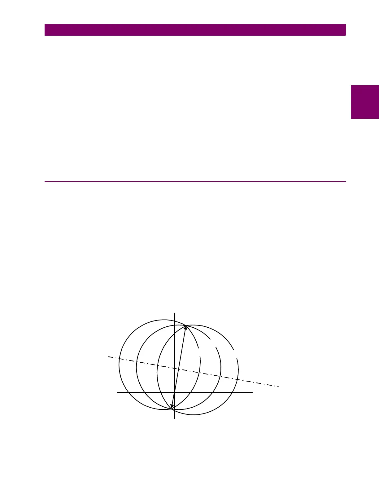
from the regular LPS-O distance functions) as shown in Figure 2–12: OUT-OF-STEP TRIPPING. For an
out-of-step condition, the apparent impedance seen by the relay will follow a typical swing line as shown below.
An out-of-step condition is recognized by sensing that the apparent impedance seen by the system first enters
the outer characteristic, then the middle characteristic, and finally the inner characteristic. The traversal from
characteristic to characteristic occurs in a finite time that is directly related to the slip frequency of the power
system during an out-of-step condition.
The following settings must be made (refer to Figure 2–13: OST REACH CHARACTERISTIC). It will most
likely be necessary to run load flow and system swing studies to determine the settings for any given applica-
tion. The example used below is provided only for use as a guide in describing each of the settings.
Figure 2–12: OUT-OF-STEP TRIPPING
Outer
Middle
Inner
Swing Line
R
X
Zf
Zr