1-
8
LPS-O Line Protection System GE Power Management
1.4 AUXILIARY PROTECTION FUNCTIONS 1 PRODUCT DESCRIPTION
1
1.4 AUXILIARY PROTECTION FUNCTIONS 1.4.1 POTENTIAL TRANSFORMER FUSE FAILURE (PTFF)
Because distance or directional functions may operate for a full or partial loss of AC potential caused by one or
more blown fuses, PTFF is provided to block distance and directional function tripping when a fuse failure is
detected. If the backup overcurrent functions (50, 50G, and 51G) are not directionally controlled, they are
allowed to trip during a potential fuse failure condition. If any backup overcurrent function (50, 50G or 51G) is
directionally supervised, then it is not allowed to trip; rather, a second overcurrent function (50_FF, 50G_FF, or
51G_FF) is placed in service during the fuse failure condition. The pickup level setting of these functions is
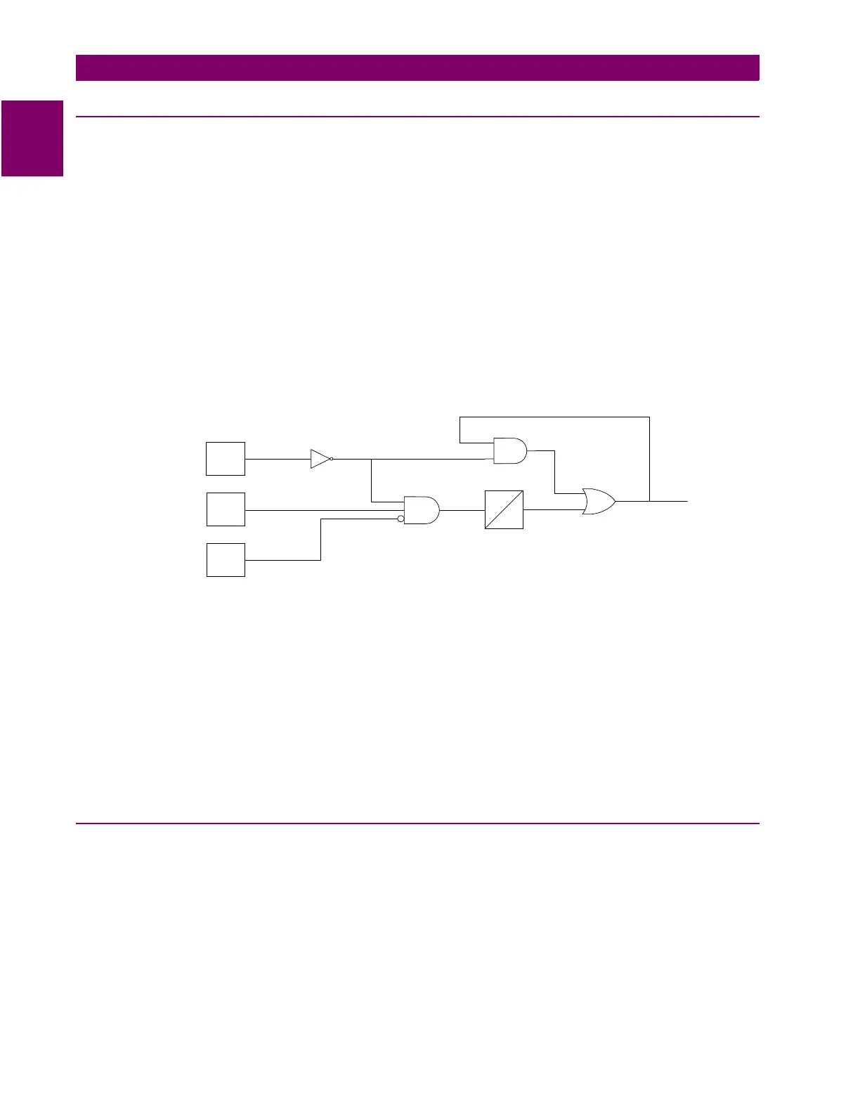
independent from the normal pickup setting. Figure 1–1: PTFF LOGIC DIAGRAM shows the functional logic for
the PTFF function.
If AC potential is lost on one or more phases, the voltage detector produces a logic 0 output which is inverted
and fed to the upper input of AND1. The phase undervoltage pickup setting is fixed at 75% of nominal and the
pickup-to-dropout ratio is virtually 100%. The lower input to AND1 is dependent upon whether the fault detector
FD has operated or whether one or more phases of the protected line are de-energized (open). When one or
more phases of protected line are open, PTFF is disabled.
Figure 1–1: PTFF LOGIC DIAGRAM
If AC potential is lost for any reason, including a blown fuse or fuses, and there is no disturbance on the power
system so that the fault detector has not operated, AND1 produces an output that causes timer TL1 to time out
and produce a PTFF output via OR2. The output of OR2 is routed to AND2 to seal in the PTFF output, based
on the voltage detector output. As such, the PTFF output is maintained as long as the potential is below nor-
mal. Protection Setting 705:
FUSEFAIL
determines whether PTFF operation blocks distance/directional trip-
ping (
FUSEFAIL
= YES) or merely issues an event (
FUSEFAIL
= NO). When the potential returns to normal,
the voltage detector resets to remove the seal-in, allowing the PTFF output to reset.
When a fault occurs, with an attendant drop in potential, the voltage detector picks up, but the fault detector
operates to prevent an output from AND1. PTFF does not operate on fault conditions.
1.4.2 LINE PICKUP
The Line Pickup (Close-onto-Fault) logic provides tripping in the event that the breaker is closed into a zero-
voltage bolted fault (for example, if grounding chains were left on the line following maintenance). For this
three-phase zero voltage fault, the Mho distance functions can not operate because they do not have a source
of polarizing voltage. Figure 1–2: LINE PICKUP LOGIC DIAGRAM shows the functional logic for Line Pickup
on the LPS-O.
3~
0
V1
IB
FD
FAULT
DETECTOR
VOLTAGE
DETECTOR
CURRENT
DETECTOR
2
1
TL1
PTFF
1
2