GE Power Management LPS-O Line Protection System 3-
1
3 HARDWARE DESCRIPTION 3.1 CASE ASSEMBLY
3
3 HARDWARE DESCRIPTION 3.1 CASE ASSEMBLY 3.1.1 CONSTRUCTION
CAUTION:
Power down the relay by turning off the front panel power switch and disconnect-
ing power from the rear connector (A1–A17) before disassembling the unit. Failure to do so
can permanently damage the relay.
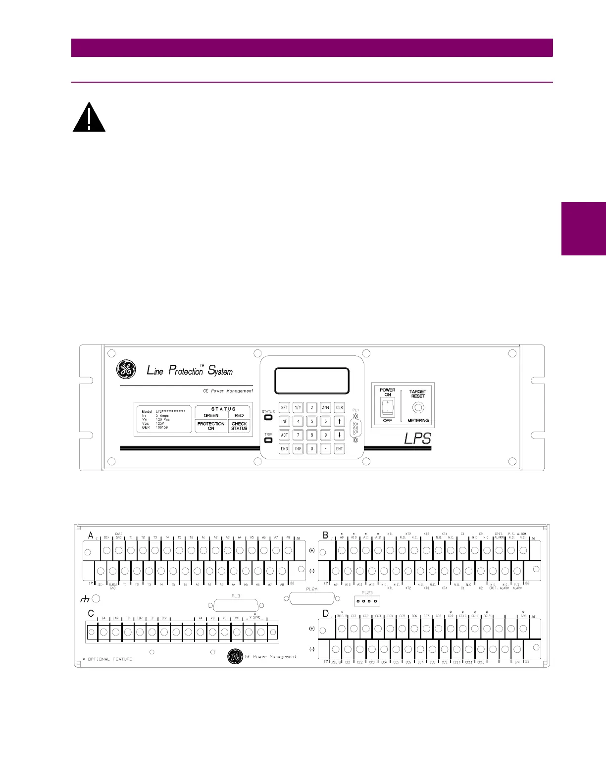
The LPS-O case is constructed from an aluminum alloy. It consists of a main frame with mounting brackets and
a front, top and rear cover. The relay may be mounted either vertically or horizontally, and mounting ears may
be placed in 6 positions (see Figure 3–1: FRONT AND REAR VIEWS OF THE LPS-O).
The front cover attaches with four thumb screws. A hole in each of the screws permits a tamper proof installa-
tion when a sealing wire is passed through two or four thumbscrews. The Target Reset / Metering button is
accessible via a hole in the front cover. place by restraining screws on the front of the module trays.
The rear of the case supports terminal blocks for external connections to the relay. The printed circuit boards
are mounted horizontally inside the case and connected via a bus card behind the front panel. They also have
rear edge connectors that electrically connect with the rear terminal blocks, and are firmly held in place by
restraining screws on the front of the module trays.
Each board is mounted on an aluminum plate. Proper alignment of the boards to their sockets is maintained by
card guides. The aluminum plate supporting each board fits into these guides. The magnetics module, due to
its weight, is rigidly mounted to the bottom of the case.
Figure 3–1: FRONT AND REAR VIEWS OF THE LPS-O
4 3 2 1
LPS-O – Line Protection System