1-
10
LPS-O Line Protection System GE Power Management
1.4 AUXILIARY PROTECTION FUNCTIONS 1 PRODUCT DESCRIPTION
1
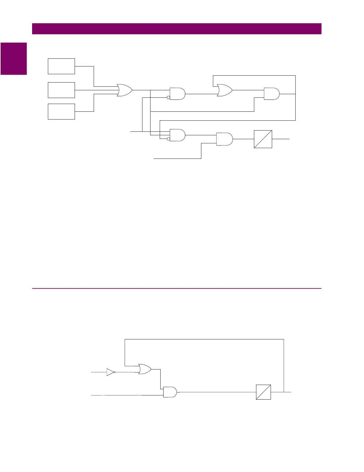
Figure 1–3: REMOTE-OPEN DETECTOR LOGIC
If charging current is initially detected but the fault detector (FD) is not picked up, indicating no fault on the
power system, then OR1 and AND1 produce outputs. AND2 produces an output and seals itself in on the out-
put of OR1 via OR2. AND3 is now blocked from producing an output as long as charging current is detected,
regardless of whether FD is picked up. If a subsequent fault occurs and the remote breaker opens, ROD is pre-
vented from producing an output.
If sufficient load current is flowing prior to the fault, then there is no output from OR1, indicating that no charg-
ing current is detected, and AND3 is not blocked, since there is no output from AND2. If an unbalanced fault
subsequently occurs, FD blocks AND1 to prevent an AND2 output. AND3 is allowed to produce an output
when the remote breaker opens, provided there is sufficient charging current to operate one or more of the
three charging-current-detectors that are the inputs to OR1. The capacitive charging current must be 60 mA or
more (secondary phase current) to assure operation of ROD. If the fault is still present an ROD trip follows the
expiration of the TL20 security time delay.
1.4.4 OUT-OF-STEP BLOCKING
Figure 1–4: OSB LOGIC DIAGRAM and Figure 1–5: OSB R-X DIAGRAM represent the functional logic for out-
of-step blocking and the R-X diagram depicting an assumed swing-impedance locus superimposed on the
associated distance relay characteristics. For an out-of-step condition, the impedance locus will first enter the
MOB characteristic, then afterwards the MT (phase-distance trip function) characteristic.
Figure 1–4: OSB LOGIC DIAGRAM
A
0
IA LEADS
VA BY 90°
IB LEADS
VB BY 90°
IC LEADS
VC BY 90°
FAULT
DETECTOR
ANY ZONE2
PHASE-DISTANCE
FUNCTION
1
1
2
2
4
3
A = 10 to 100
TL20
TRIP
*
50
*
30 ms. INITIAL PICKUP TIME
ADAPTIVE AFTER FIRST SLIP CYCLE
TL1
OSB
202
202
ANY COORDINATING
ZONE
ANY MOB