GE Power Management LPS-O Line Protection System 2-
21
2 CALCULATION OF SETTINGS 2.3 PROTECTION SETTINGS
2
801: LINEPICKUP - Select Line Pickup
Set
LINEPICKUP
= YES if the line pickup logic is to be used, otherwise set
LINEPICKUP
= NO.
802: BYPASSTL3 - Bypass Line Pickup Time Delay
If simultaneous reclosing is used and if
I1PICKUP
(Protection Setting 803) must be set below full load, then set
BYPASSTL3
= NO, otherwise set
BYPASSTL3
= YES.
803: I1PICKUP - I1 Pickup Setting
I1 is the overcurrent trip unit used in the Line Pickup function, and it operates on the magnitude of the posi-
tive-sequence current.
I1PICKUP
should be set no greater than two-thirds of the minimum fault current for an internal three-phase
fault at the relay location. If the minimum fault current is greater than the maximum load current on the pro-
tected line, then the I1 setting can be reduced to provide greater coverage of the line. For this case, a setting of
110% of the maximum load current is proposed.
2.3.10 REMOTEOPEN
The Remote-Open Detector (ROD) function issues a trip signal when the remote breaker opens during an
unbalanced internal fault. This function detects that the remote breaker has opened by recognizing charging
current on one or more phases following opening of the remote breaker. The Remote-Open Detector will not
operate for a balanced three phase fault.
ROD logic can speed up tripping at the end of the line that otherwise would be the slowest to respond in a
sequential-tripping condition. In a Step Distance scheme, ROD tripping is beneficial for any unbalanced inter-
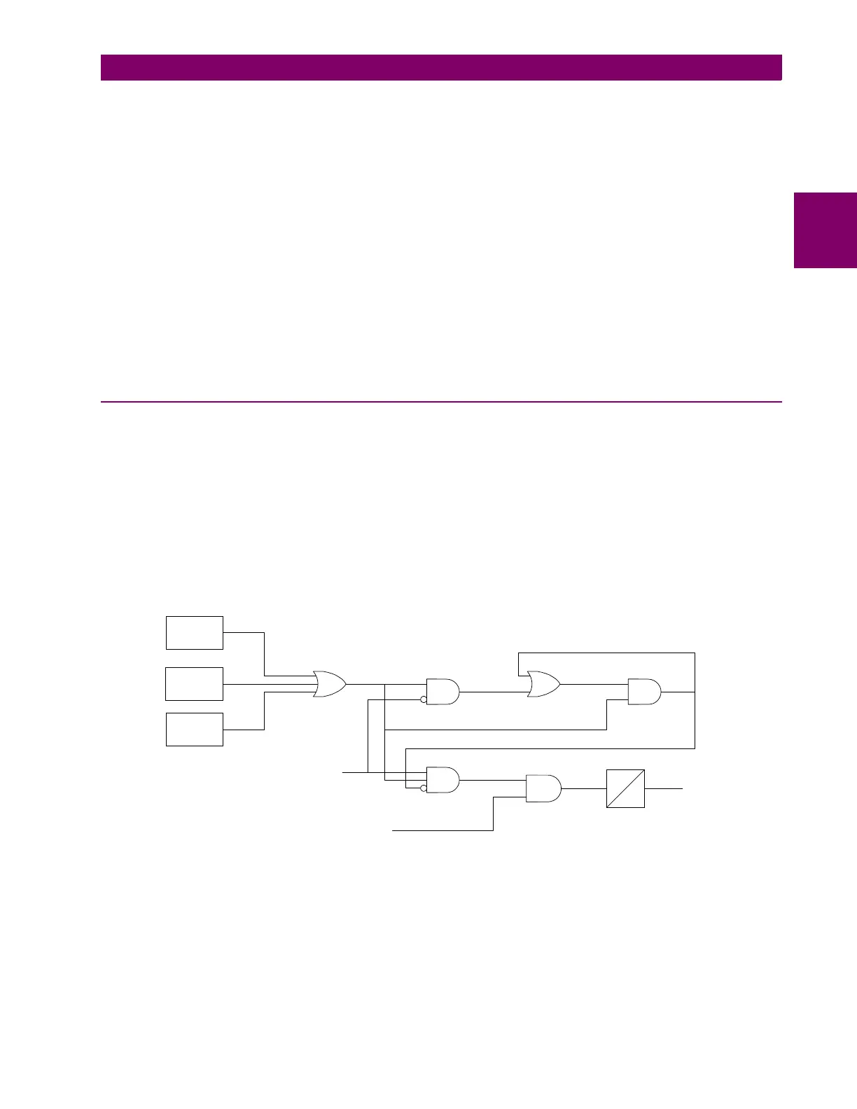
nal fault not detected by Zone 1. Figure 2–9: ROD LOGIC DIAGRAM is a functional logic diagram of the ROD
function. The sequence of events that results in an ROD output is as follows:
Figure 2–9: ROD LOGIC DIAGRAM
1. No charging current is detected prior to the fault – logic 0 output from AND2.
2. A fault is detected – logic 1 output from OR3.
3. The remote breaker opens and charging current is detected – logic 1 output from AND3.
4. The fault is still present, so the two inputs to AND4 persist and a trip output will be produced following the
time-delay setting of timer TL20.
A
0
IA LEADS
VA BY 90°
IB LEADS
VB BY 90°
IC LEADS
VC BY 90°
FAULT
DETECTOR
ANY ZONE2
PHASE-DISTANCE
FUNCTION
1
1
2
2
4
3
A = 10 to 100
TL20
TRIP



 To Next Page