GE Power Management LPS-O Line Protection System 2-
15
2 CALCULATION OF SETTINGS 2.3 PROTECTION SETTINGS
2
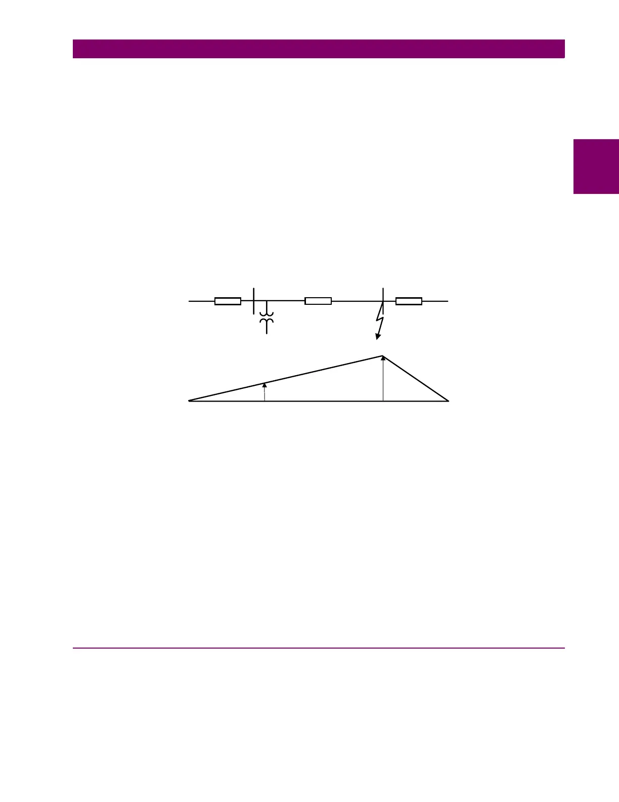
In this system, the voltage (
V
) at the relay is in the proper direction to provide correct directional sensing, but,
depending on the source to line impedance ration (Zs/ZL), the magnitude of the voltage may not be sufficient to
provide a reliable polarizing quantity. The problem is most onerous on a long transmission line with a strong
source impedance behind the relay (Zs/ZL is quite small). The effect of the offset in this case is to add a com-
ponent to the actual voltage so as to replicate the voltage at a point some distance down the transmission line.
NT_OFFSET
can be determined as follows:
NT
_
OFFSET
= 0.005·
Z
1
·
I
n
where
Z
1
= positive sequence impedance of protected line (in secondary ohms)
I
n
= Magnetics Module CT rating (1A or 5A)
If the calculated value is greater than 0.05, then set
NT_OFFSET
= 0.05. Otherwise, use the calculated value
and make the next lowest available setting. For example, if the calculated setting is 0.027, set
NT_OFFSET
=
0.02
Figure 2–6: NT/NB FUNCTIONS
507: UNBALALARM - Unbalanced Current Alarm
The LPS-O system is supervised by a fault detector (FD) that uses the following operating quantity:
FD
op
=
Tripping will not be permitted unless there is a concurrent output from the fault detector, resulting in an
increase of security. The LPS-O system monitors the output of the fault detector. If it produces an output that
lasts for more than 60 seconds, then it is an indication that:
1. there is an unbalance in the current on the system as indicated by the presence of negative-sequence cur-
rent (
I
2
) and/or zero-sequence current (
I
0
), or
2. the fault detector has failed (unlikely).
If either of these conditions is detected an
UNBALARM
signal is produced. This signal can be routed via the
Xpression Builder program to drive one of the programmable outputs, or it may be used as an input to one of
the programmable outputs that may already have been selected for alarm duty.
2.3.7 OVERCURRNT
601: 50 - Phase Instantaneous Overcurrent
The
50
function can be used in many applications to provide high speed, direct tripping for heavy close-in
faults. To use the phase instantaneous overcurrent trip function, set
50
= YES, otherwise set
50
= NO. See
Protection Settings 602 and 603 for further discussion on use of
50
function. Also, Protection Setting 201:
Z2PHASE
must be set to YES.
Zs ZL
Xc
VF
V
Vf
Xc > Zs
I
∆
1
I
2
I
0
++