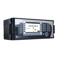
GE Power Management LPS-O Line Protection System
i
INDEX
INDEX
Numerics
50 (Protection Settin
601)......................................... 2-15
50 FUNCTION
PTFF ........................................................................ 1-8
50_DIRCNL (Protection Settin
602) .......................... 2-16
50G (Protection Settin
605) ...................................... 2-16
50G FUNCTION........................................................... 1-5
PTFF ........................................................................ 1-8
50G_DIRCNL (Protection Settin
606) ........................ 2-16
50GPICKUP (Protection Settin
607).......................... 2-16
50GPICKUPFF (Protection Settin
608)...................... 2-17
50PICKUP (Protection Settin
603) ............................ 2-16
50PICKUPFF (Protection Settin
604) ........................ 2-16
51G (Protection Settin
610) ...................................... 2-17
51G FUNCTION........................................................... 1-5
characteristic curve shape ....................................... 2-18
directional control.................................................... 2-17
operatin
quantity.................................................... 2-17
pickup ..................................................................... 2-17
PTFF ........................................................................ 1-8
settin
..................................................................... 2-17
time-dial settin
....................................................... 2-18
51G_RESET (Protection Settin
617) ......................... 2-18
51GCURVE (Protection Settin
614)........................... 2-18
51GDIRCNL (Protection Settin
611).......................... 2-17
51GPICKUP (Protection Settin
612).......................... 2-17
51GPICKUPFF (Protection Settin
613)...................... 2-17
51GTIMDIAL (Protection Settin
615) ......................... 2-18
52/A CONTACT ......................................................... 1-15
52/B CONTACTS ....................................................... 1-15
A
A1 (Protection Settin
1607) ...................................... 2-28
A10 (Protection Settin
1616) .................................... 2-28
A11 (Protection Settin
1617) .................................... 2-28
A12 (Protection Settin
1618) .................................... 2-28
A2 (Protection Settin
1608) ...................................... 2-28
A3 (Protection Settin
1609) ...................................... 2-28
A4 (Protection Settin
1610) ...................................... 2-28
A5 (Protection Settin
1611) ...................................... 2-28
A6 (Protection Settin
1612) ...................................... 2-28
A7 (Protection Settin
1613) ...................................... 2-28
A8 (Protection Settin
1614) ...................................... 2-28
A9 (Protection Settin
1615) ...................................... 2-28
AC SYSTEM INPUT TEST.......................................... 4-14
ACCEPTANCE/PERIODIC TESTS
AC system input test................................................ 4-14
description ................................................................ 4-1
di
ital output test..................................................... 4-10
drawin
s ................................................................... 4-1
enterin
test mode..................................................... 4-8
exitin
test mode ....................................................... 4-8
eneral instructions ................................................... 4-2
eneral relay tests..................................................... 4-1
initial test setup......................................................... 4-8
keypad test ............................................................... 4-9
references................................................................. 4-1
relay status ............................................................... 4-9
required settin
s ....................................................... 4-2
settin
chan
es......................................................... 4-3
test equipment .......................................................... 4-1
test setup.................................................................. 4-6
test unit description ................................................... 4-6
ACCURACIES ............................................................. 7-2
ACTIVE SETTINGS GROUP
selectin
................................................................... 8-8
selectin
with LUI ...................................................... 8-8
ADAPTIVE MEMORY
Zone 4 phase distance functions ...............................2-13
ALARMS
critical......................................................1-15, 1-18, 4-3
description ...............................................................1-15
line overload ............................................................1-15
non-critical ...............................................................2-27
overcurrent ..............................................................1-15
power supply............................................................1-15
trip circuit.................................................................1-15
unbalanced current..........................................1-15, 2-15
zone fla
s on ...........................................................1-15
ALPS-TEST
close test file............................................................10-9
copyin
mho circles ................................................10-12
description ...............................................................10-1
edit menu......................................................10-2, 10-12
enterin
input quantities ...........................................10-3
enterin
values................................................10-4, 10-5
exitin
pro
ram ......................................................10-11
file menu.........................................................10-2, 10-8
help menu ..............................................................10-17
initial screen ............................................................10-1
input test dialo
box .................................................10-4
M1 phase units................................................10-4, 10-5
M3 phase units.........................................................10-6
M4 phase units................................................10-6, 10-7
MOB phase unit........................................................10-7
MT phase units.........................................................10-6
new test file .............................................................10-8
open settin
file........................................................10-8
printin
..................................................................10-11
save input quantities...............................................10-10
save output ............................................................10-10
selectin
values .......................................................10-5
startin
for first time .................................................10-1
status bar...............................................................10-13
test calculations ..............................................10-2, 10-3
toolbar ...................................................................10-13
tools menu .............................................................10-14
version number ......................................................10-17
view menu..............................................................10-13
viewin
multiple tests .............................................10-16
window menu .........................................................10-16
ANI
see DSP / ANI / COMM/ LUI MODULE
APPLICATIONS OF THE LPS-O................................... 1-4
ARROW KEYS............................................................. 8-3
ASCII COMMAND LIST ...............................................12-2
ASCII COMMUNICATIONS .........................................12-1
ASCII INTERFACE ............................................8-26, 12-1
ASCII PROMPTS ........................................................12-1
AUXILIARY PROTECTION FUNCTIONS ....................... 1-8



 To Next Page