2-
32
LPS-O Line Protection System GE Power Management
2.5 REFERENCE TABLES 2 CALCULATION OF SETTINGS
2
2.5 REFERENCE TABLES 2.5.1 INDEX NUMBERS
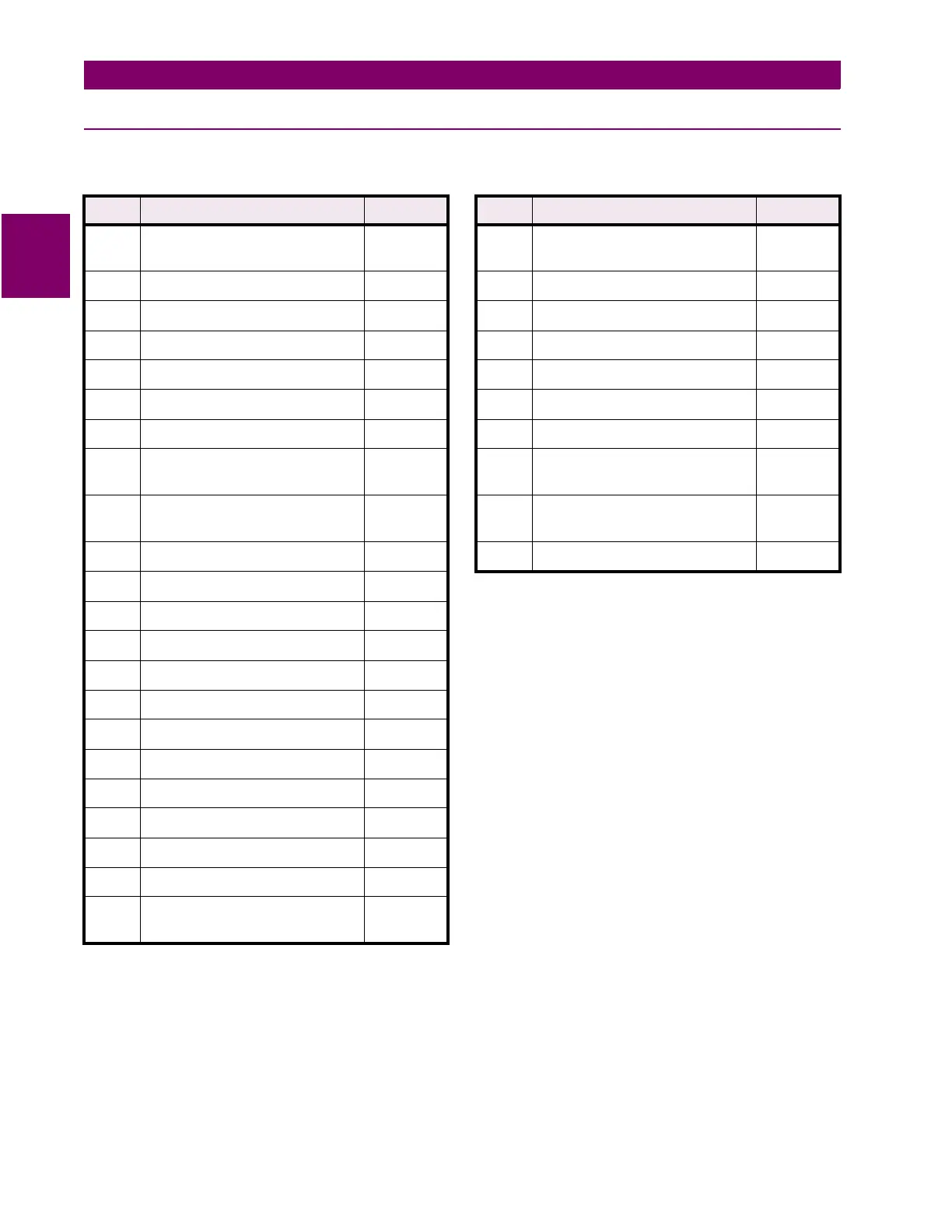
Table 2–5: INDEX NUMBERS – CONTACT CONVERTER INPUT ASSIGNMENT
Index Description
Mnemonic
Index Description
Mnemonic
1 Breaker #1 52b Contact Input 52B_1 23 External Contact Input to Trigger
Oscillography Capture
OSCTRG
2 Spare 24 Spare
3 Spare 25 CONFIGURABLE INPUT1 CNFDI2
4 Breaker #2 52b Contact Input 52B_2 26 CONFIGURABLE INPUT2 CNFDI2
5 Spare 27 CONFIGURABLE INPUT3 CNFDI3
6 Spare 28 CONFIGURABLE INPUT4 CNFDI4
7 Spare 29 CONFIGURABLE INPUT5 CNFDI5
8 Change Setting Group Input
(BIT0)
CGST1 30 CONFIGURABLE INPUT6 CNFDI6
9 Change Setting Group Input
(BIT1)
CGST2 31 CONFIGURABLE INPUT7 CNFDI7
10 Spare 32 CONFIGURABLE INPUT8 CNFDI8
11 Spare
12 Spare
13 Spare
14 Spare
15 Spare
16 Spare
17 Spare
18 Spare
19 Spare
20 Spare
21 Spare
22 External Contact Input to Disable
Outputs
DISOUT
Note
: Any of the above signals (1 to 32) may be assigned to the 12 available LPS-O Contact Converter
Inputs (CC1 to CC12). Those 12 signals will also be available for use for the Programmable Outputs and/or
the Configurable Logic. Unassigned signals will NOT be available.