GE Power Management LPS-O Line Protection System 2-
19
2 CALCULATION OF SETTINGS 2.3 PROTECTION SETTINGS
2
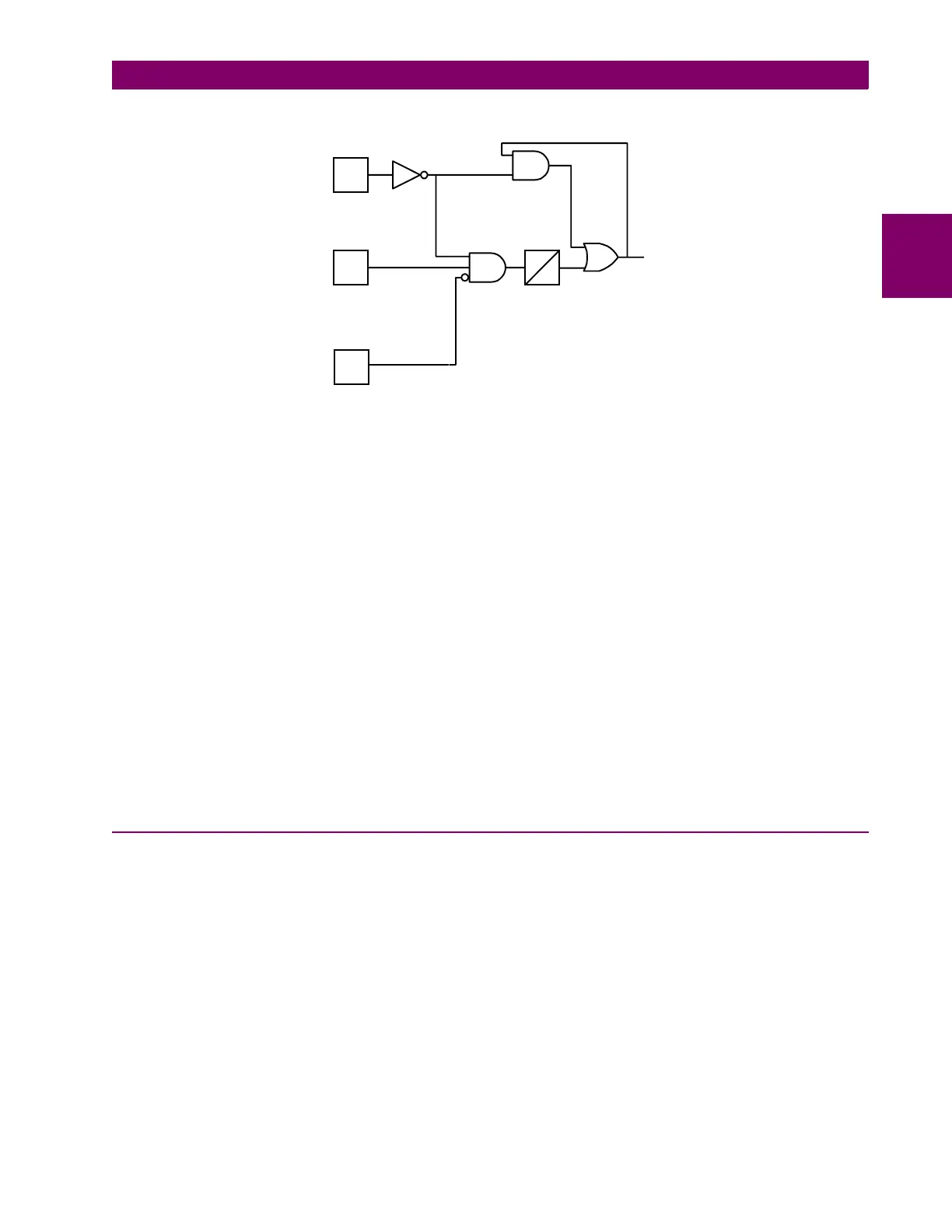
Figure 2–7: FUSEFAIL FUNCTION LOGIC DIAGRAM
If AC potential is lost, the positive-sequence voltage detector V1 drops out, NOT1 produces a logic 1 output,
and the upper input is present at AND1. The V1 pickup setting is fixed at 75% of
RATEDVOLTS
. The middle
input to AND1 is present if load current is sufficient to operate the current detector IB, while the bottom input is
dependent upon whether the fault detector FD has operated or whether one or more poles of the breaker are
open.
If AC potential is lost for any reason, including a blown fuse or fuses, and there is no disturbance on the power
system so that the fault detector has not operated, AND1 produces an output that causes timer TL1 to time out
and produce a
FUSEFAIL
output via OR2. The output of OR2 is routed to AND2 to seal in the
FUSEFAIL
out-
put, based on the output of V1, so that
FUSEFAIL
output is maintained as long as the potential is below nor-
mal. When the potential returns to normal, V1 and NOT1 reset to remove the seal-in, allowing the
FUSEFAIL
output to reset.
When a fault occurs, with an attendant drop in potential, the V1 function resets, but the fault detector operates
to prevent an output from AND1.
FUSEFAIL
does not operate on fault conditions.
FUSEFAIL
can be set to NO or YES. If YES is selected, then an output will be prevented from any function that
requires potential to operate (distance, directional and any directionally controlled function). If NO is selected,
nothing will be blocked in the event a potential failure occurs.
2.3.9 LINEPICKUP
Line Pickup provides tripping in the event that the breaker is closed into a zero-voltage bolted three-phase
fault, such as occurs if the grounding chains are left on the line following maintenance. Figure 2–8: LINE
PICKUP FUNCTIONAL LOGIC shows the functional logic for Line Pickup.
V1
IB
FD
3
1
1
2
2
0
FUSEFAIL
VOLTAGE
DETECTOR
CURRENT
DETECTOR
FAULT
DETECTOR