GE Power Management LPS-O Line Protection System 2-
9
2 CALCULATION OF SETTINGS 2.3 PROTECTION SETTINGS
2
2.3 PROTECTION SETTINGS 2.3.1 Z1DISTANCE
101: Z1PHASE - Zone 1 Phase Distance Functions
Set
Z1PHASE
equal to YES if Zone 1 protection for phase faults is desired. Otherwise set
Z1PHASE
equal to
NO. It is highly desirable to use Zone 1 protection in all schemes because it provides independent, high speed
direct tripping for all phase faults within the reach setting.
102: Z1PREACH
If potential transformers (PTs) are used, use a reach setting that is no greater than 90 percent of the positive-
sequence impedance of the line to be protected.
103: (NOT USED)
104: Z1P_TIME - Zone 1 Phase Timer
Z1P_TIME
can be set from 0.0 to 10.0 seconds and establishes the time delay that the Zone 1 phase functions
can be picked up before tripping is initiated. It should be set to zero for traditional Zone 1 application for line
protection. For the system backup application, it should be set with appropriate delay consistent with the reach
setting.
2.3.2 ZONE 2, ZONE 3, AND ZONE 4 DISTANCE FUNCTIONS
The reach setting to be used on the Mho type distance functions will be established by the specific application.
It must not exceed the maximum allowable reach which is dependent on the following:
1. Shape of the characteristic: circle or lens.
2. Angle of maximum reach.
3. Maximum amount of load flow transferred across the transmission line.
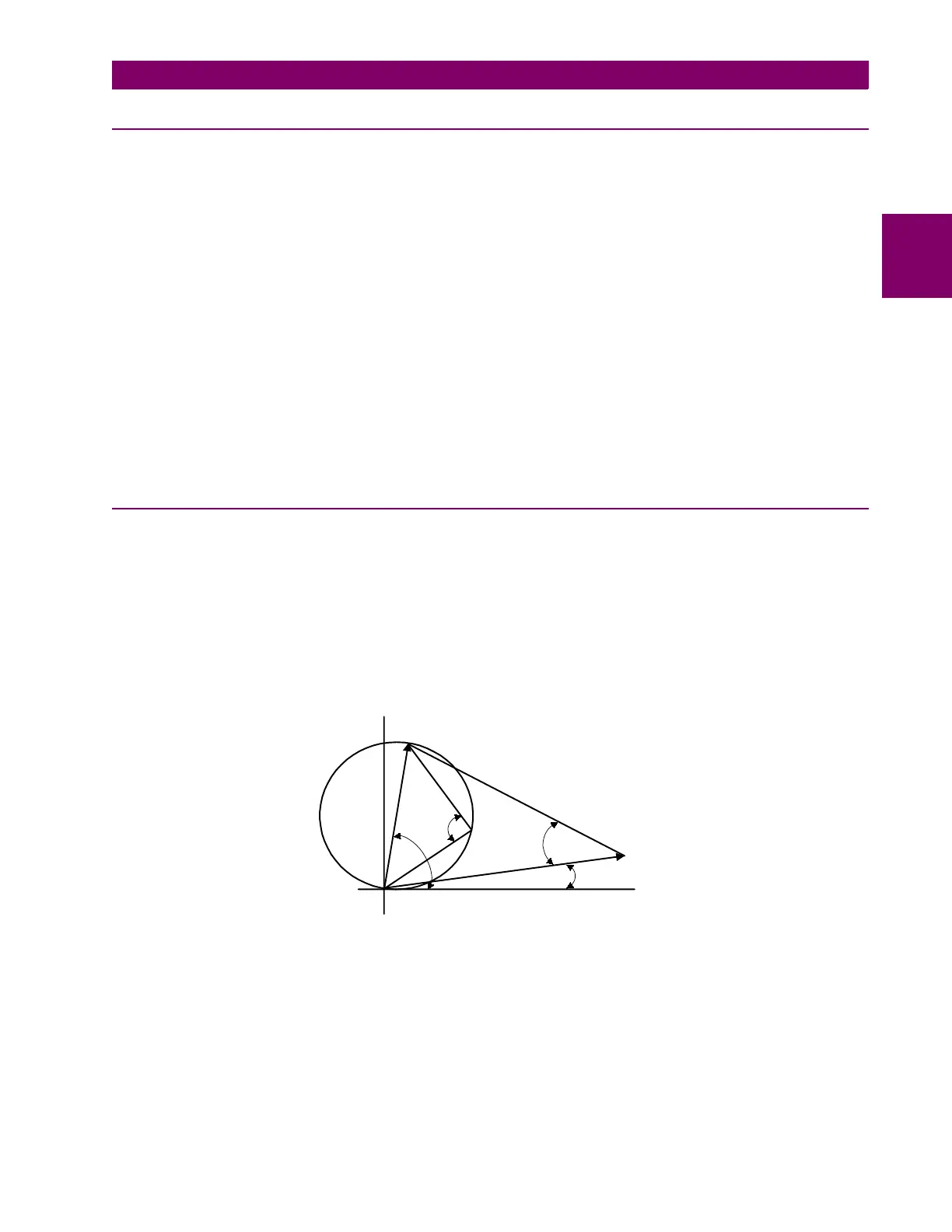
Figure 2–2: MAXIMUM ALLOWABLE REACH
X
R
B
C*
D*
MR
MR = Maximum Allowable Reach
D = Angle of Maximum Reach
C = Load Impedance Angle
*Measured counterclockwise
from R axis
ZL
ZL = Load Impedance
A
B = Characteristic Angle; < 90 = Lens