3-
2
LPS-O Line Protection System GE Power Management
3.1 CASE ASSEMBLY 3 HARDWARE DESCRIPTION
3
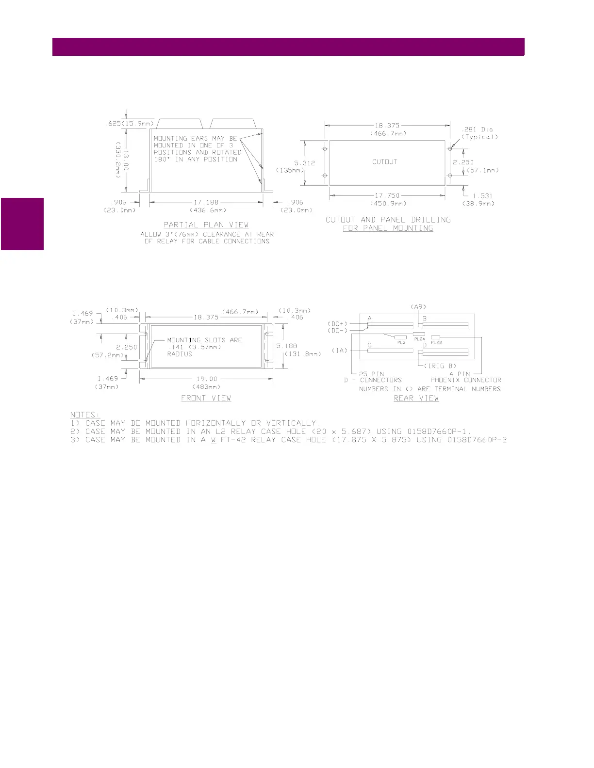
Figure 3–2: LPS-O OUTLINE – HORIZONTAL
An outline drawing is shown in Figure 3–2: LPS-O OUTLINE – HORIZONTAL above, presenting the front, top,
and rear views of the horizontal mount LPS-O. This figure provides a panel cutout and drill pattern for mounting
the LPS-O.