GE Power Management LPS-O Line Protection System 2-
45
2 CALCULATION OF SETTINGS 2.5 REFERENCE TABLES
2
OSC_GRAPHY
301 NUMFAULTS Number of Fault Records
(with expanded memory)
6, 12, 24, 36 none N/A
302 PREFAULT Number of Pre-fault Cycles 1 to 8 1 5
303 SPLITREC Splits Fault Record and
captures this percentage at
end, with 1-SPLITREC
captured at beginning
0 to 100% 1 0
BRKR DUTY
401
EXPONENT
Exponent in
I
x
t
calculation
1.0 to 2.0 0.1 2.0
402 MAX_OP Maximum Number of
Breaker Operations for a
Breaker
0 to 9999 1 0
403 MAX_IXT Maximum Breaker Duty for
a Breaker
0 to 9999999 A
x
sec.
0.1K
0
404 IXTPHASEA Accumulated Breaker Duty,
Phase A
0 to 9999999 A
x
sec.
0.1K
0
405 IXTPHASEB Accumulated Breaker Duty,
Phase B
0 to 9999999 A
x
sec.
0.1K
0
406 IXTPHASEC Accumulated Breaker Duty,
Phase C
0 to 9999999 A
x
sec.
0.1K
0
407 NUM_OP Present Number of Breaker
Operations
0 to 9999 1 0
INPUTS
501
CC1
Contact Converter 1
0 to 32
‡
10
502 CC2 Contact Converter 2
0 to 32
‡
10
503 CC3 Contact Converter 3
0 to 32
‡
10
504 CC4 Contact Converter 4
0 to 32
‡
10
505 CC5 Contact Converter 5
0 to 32
‡
11
506 CC6 Contact Converter 6
0 to 32
‡
1
4
507 CC7 Contact Converter 7
0 to 32
‡
10
508 CC8 Contact Converter 8
0 to 32
‡
10
509 CC9 Contact Converter 9
0 to 32
‡
10
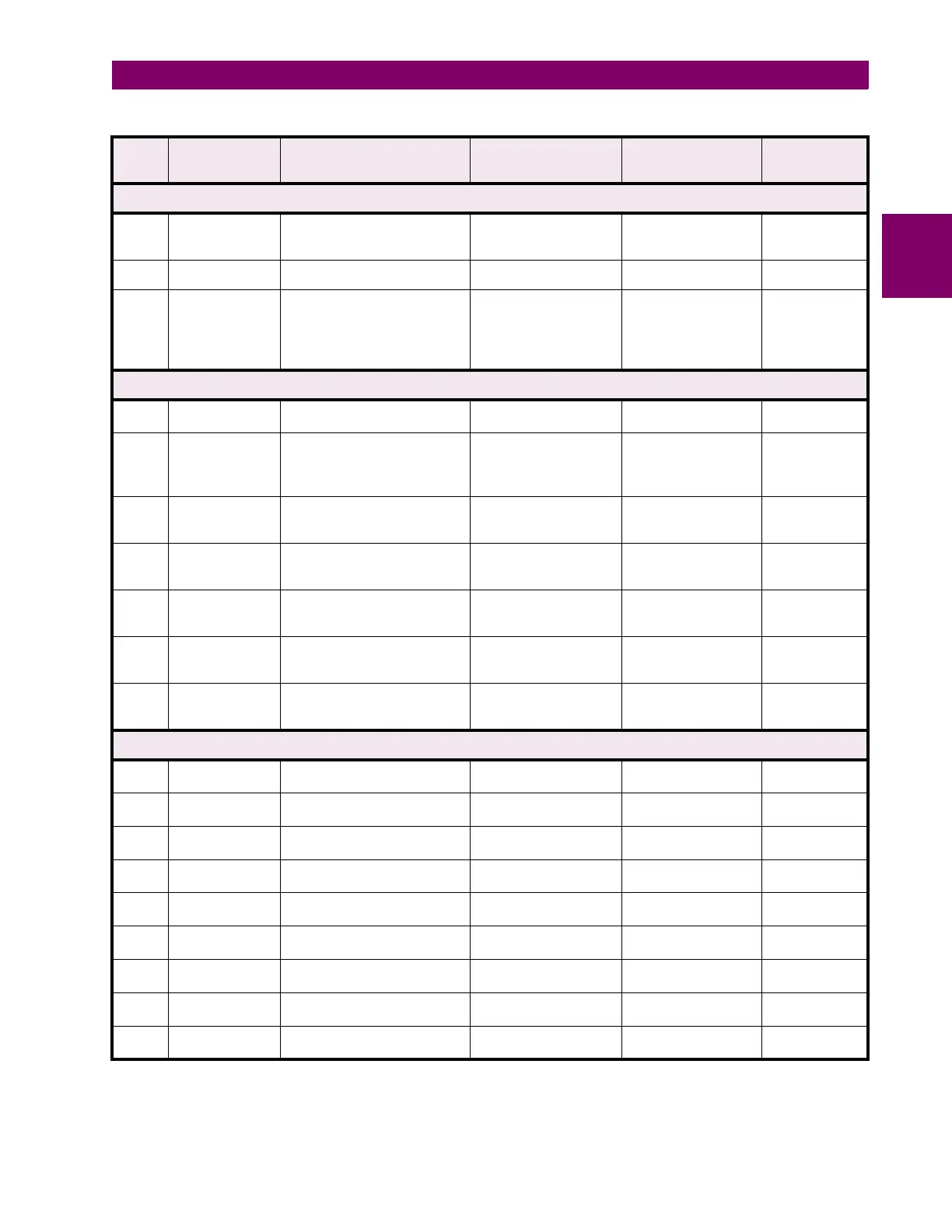
Table 2–8: GENERAL SETTINGS GUIDE (Sheet 2 of 3)
No.
Mnemonic
Description Range
(5A & 1A)
Step Default
‡
Contact Converter output normally appears as a Logic 1 with normally open contact connected; to invert
output to Logic 0, add 1000 to the number