14 SD Series Technical Manual MDS 05-4846A01, Rev. D
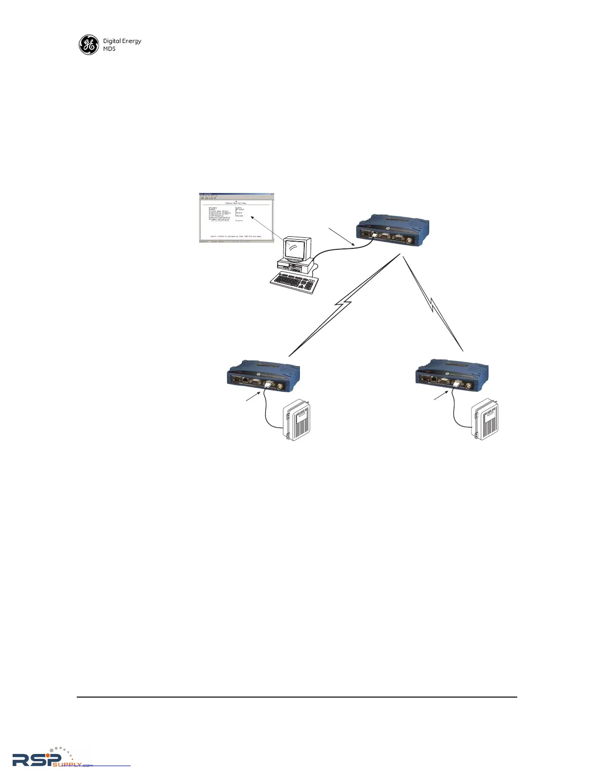
In this example, the Host Computer is connected directly to the radio’s
Ethernet port, and the RTUs at the Remote sites are connected to the
transceiver via the radio’s COM2 serial data ports. The IP Payload fea-
ture, used at the master, efficiently passes TCP payload over the air, and
eliminates the need for an external terminal server. (COM1 may also be
used for payload data if properly configured via the management
system. See next example.)
Invisible place holder
Figure 9. IP Polling of Serial Remotes
Serial Remotes with Two Serial Ports
In some cases, it is necessary to poll more than one RTU at a Remote
site. Figure 10 shows an example of this type of system. Here, two
RTUs are connected to each Remote transceiver, by using both of the
radio’s serial ports—COM1 and COM2.
By default, the radio’s COM1 port is configured for serial management
functions with a connected PC, but it may be configured for data service
using the management system. This arrangement allows two telemetry
networks to share a single radio system.
In such a system, each RTU gets every message from the host computer,
and the underlying protocol (e.g., Modbus, DNP, etc.) sorts out which
messages are applicable to a specific RTU.