16 SD Series Technical Manual MDS 05-4846A01, Rev. D
4.0 INSTALLATION PLANNING
This section discusses the factors to be considered before installing the radio.
Careful planning of the installation site will help achieve optimal performance
from the transceiver. Step-by-step installation procedures begin on Page 25.
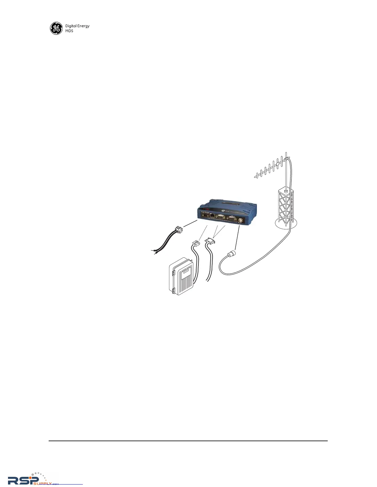
Figure 11 shows a typical remote station arrangement. The specific details at
an installation site may vary, but there are three main requirements for
installing the transceiver in all cases:
• Adequate and stable primary power
• An efficient and properly installed antenna system
• Correct interface connections between the transceiver and the data
device.
Figure 11. Typical Station Arrangement (Remote shown)
4.1 Mounting Options
The transceiver is normally provided with flat mounting brackets
attached to the bottom of the radio as shown in Figure 12. An optional
35mm DIN rail mounting bracket is also available, and is described
below.
RSPSupply - 1-888-532-2706 - www.RSPSupply.com
http://www.RSPSupply.com/p-8461-MDS-UP-SD9-MS2ES-Upgrade-Key-SD9-MS-to-SD9-ES.aspx