30 SD Series Technical Manual MDS 05-4846A01, Rev. D
3. If not done earlier, refine the antenna heading of the station to maxi-
mize the received signal strength (RSSI) from the Master Unit. The
Performance screen may be used to observe RSSI. Turn the antenna
heading slowly so that the RSSI display can be updated.
NOTE: The RSSI facility limits the maximum displayed signal strength to –60
dBm.
Invisible place holder
Ethernet Connector LEDs
The 10/100 Base-T Ethernet connector has two embedded LEDs. A
flashing green indicator shows data activity, and a yellow indicates 100
Mbps operation has been achieved.
5.3 Optimizing the Radio Network
The following are additional checks/settings that you may wish to per-
form to optimize the operation of the radio system. See “USING THE
DEVICE MANAGER” on Page 33 for instructions on accessing and
changing these parameters.
Modem Type Setting
All radios in the network must be set to the same modem type and speed.
A range of values is available. The default setting is
9600. This setting
may be set/viewed using the Configuration>>Radio>>Basic Settings screen.
See Page 39 for details.
In general, the higher the modem baud rate, the faster the communica-
tion speed over the air. However, it must be remembered that signal
strength also plays a role in how fast a transmission may be sent. If sig-
nals are strong, faster speeds are possible. If signals are fair or poor,
slower speeds may be needed to achieve the best communication results
with the least number of re-transmissions due to errors.
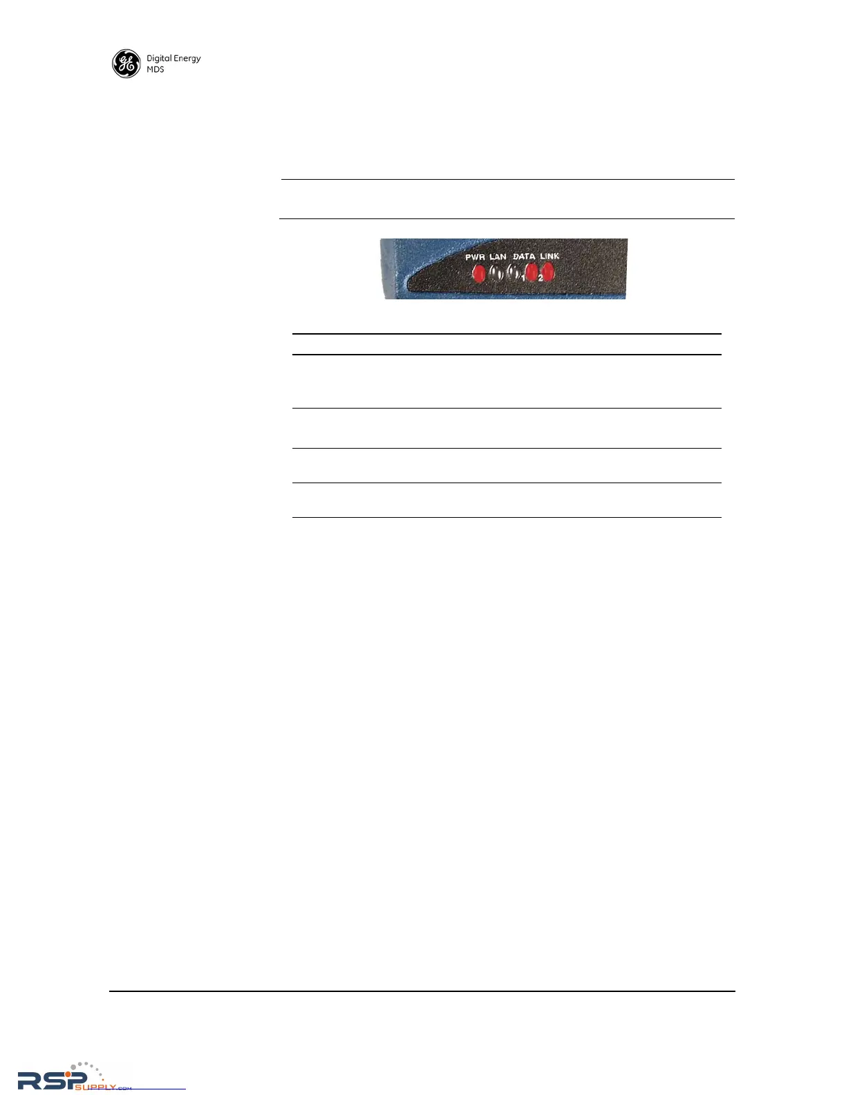
Table 10. LED Status Indicators
LED Name Description
PWR • Continuous—Power applied, no problems detected.
• Rapid flash (5 times-per-second)—Alarm indication, or
RX/TX frequencies not set.
LAN • Flashing—Data is being transmitted and received.
• Off—Ethernet signals not detected
DATA 1/DATA2 These LEDs show data activity on the DB-9 serial payload
port(s).
LINK When lit, indicates that a communication link exists with the
Master Unit.